Advertisement
Quick Links
Advertisement

Related Manuals for ThermoTek T255P

Summary of Contents for ThermoTek T255P
- Page 1 T255P User Manual...
- Page 2 Page 2 of 36 ...
- Page 3 TABLE OF CONTENTS Introduction Warnings and Cautions General Description Setting up the Thermoelectric Unit Start Up and Operating Procedures Display Messages Changing the Coolant Fluid Recommended Fluids Cleaning the Air Filter General Maintenance Service Customer Service About the Warranty Trouble Shooting Flowcharts Specifications RS232 Interface Equipment/Accessories...
- Page 4 Introduction Immediately upon receiving your new ThermoTek chiller (Recirculating Thermoelectric Heating & Cooling System) inspect your unit. If the unit shows shipping damage, contact the transportation company and file a freight damage claim. Retain all packing material and carton until the unit is operated and found to be in good condition (Please see Section 13 About the Warranty for more information).
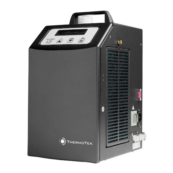
- Page 5 20. Ensure that the chiller is set up according to the instructions before energizing. General Description The T255P is a solid-state thermoelectric heating and cooling system. The unit consists of a pump, fan, electrical circuitry, and a solid-state heat transfer assembly. The T255P maintains a set temperature of the working fluid that is circulated between the thermal management application and itself.
- Page 6 Setting up the Thermoelectric Unit Connect the unit to the application using a fluid transport from ThermoTek or hoses using Colder PLC or PLCD Insert fittings. Keep unit upright and on a level surface. Make sure there is a 6-inch clearance and free path for flow of air entry and exit around the chiller prior to operation.
- Page 7 When the unit is first powered up, a green back light will be on the display screen. The messages T255P CHILLER Ver: T255 XXXX appears on the display screen located on the front of the unit. After turning the unit ON you may get a message on the display screen that reads “!!ALARMS ACTIVE!! LOW COOLANT LEVEL”...
- Page 8 Resolve by adding coolant to the system. !!ALARMS ACTIVE!! LOW TEMP ALARM: Ambient temperature too low or unit malfunction. Resolve by determining if ambient temperature is below 10°C and/or call ThermoTek service line. !!ALARMS ACTIVE!! HIGH TEMP ALARM: Application load exceeds capacity of unit, ambient temperature too high or unit malfunction.
- Page 9 The warranty is voided if the tamper seals are removed. Keep objects that obstruct the airflow away from both the inlet and exhaust fans. Service ThermoTek recommends you review the troubleshooting flowcharts before calling our customer service support group. If you still need assistance, please call our representatives at 972-874-4949. Page 9 of 36 ...
- Page 10 Customer Service Support ThermoTek Inc is committed to servicing the customer, both during and after the sale. If you have any questions concerning the operation of your unit please contact our Sales organization at our Flower Mound, Texas facility at 972-874-4949 between 8:00 am and 5:00 pm CST, Monday through Friday or you may email us at www.thermotekusa.com.
- Page 11 Power cycle the visible, unit Nuisance trip unit operating? Has the unit been power cycled 3 times? Send unit to Are the fans turning on and off? ThermoTek Power cycle the unit Is display visible? Resolved Send unit to ThermoTek Page 11 of 36 ...
- Page 12 Noisy Display Noisy/Foreign characters on display Check AC Line conditions If not within limits (100-240 VAC, 50/60 Hz) If within limits Clean input power Send to ThermoTek Note: Display may refresh every 5 minutes. This is a normal function. Page 12 of 36 ...
- Page 13 Verify circuit is not Connect chiller to overloaded. standard AC outlet Connect chiller to another AC circuit Check system Does it still Does external Check original power distribution breaker still trip? trip? AC circuit Send back to Send to ThermoTek ThermoTek Page 13 of 36 ...
- Page 14 Keypad not functional Is chiller in RS232 control? Normal operation Power cycle unit Is keypad functional after power cycle? Nuisance trip Send unit to ThermoTek Page 14 of 36 ...
- Page 15 Leaking Unit Coolant Leak Is leak at quick disconnect? Send unit to Thermotek Is quick disconnect seated Reseat quick disconnect until properly? click is heard. Call ThermoTek Customer Service Page 15 of 36 ...
- Page 16 Send unit to reservoir. Power alarm? ThermoTek See "Unit Does unit continuous alarm alarm? with coolant". Check procedure. Drain reservoir per ThermoTek Drain Procedure #200T.14 (1.9.25) Does unit Send unit to alarm w/ no ThermoTek coolant? Add coolant Does alarm Resolved...
- Page 17 Drain unit per Send unit to Does unit still Drain Procedure ThermoTek alarm? #200T.14 (1.9.25) Does unit Call ThermoTek Add coolant alarm with no Customer Service coolant? Does alarm Send unit to Problem solved clear? ThermoTek Page 17 of 36 ...
- Page 18 Re-check stability. Call Are they ThermoTek properly Call ThermoTek Send to Is it within +/- 0.1º C seated? for application ThermoTek for of set point? assistance service Note: Stability is defined as +/- 0.1 degree C of...
- Page 19 Check QD Does it reach 40 º C in 15 minutes? Set unit to 40 ºC Send unit to ThermoTek Call ThermoTek Is QD seated Set to 15 ºC or 10 Customer properly? ºC below ambient, Service whichever is...
- Page 20 5°C The performance of the chiller is based on Recirculating water with a 0.6 gpm flow. Individual applications will affect chiller performance. ThermoTek must approve all applications. Note 1: Specifications subject to change without notice. ETL tested to UL Standard 2601, CSA 22.2 CE approved with the Medical Device Directive (MDD) IEC 601-1-1, IEC601-1-2 Product Classification: Class 1, Type B Equipment;...
- Page 21 T255P Typical System Pumping Capacity Flow [US gpm] Upper Limit Lower Limit Flow [liter/min] Page 21 of 36 ...
- Page 22 T255P Typical Thermal Capacity ΔT [°F] Upper Limit Lower Limit ΔT = T(fluid out) - T(air in) ΔT [°C] NOTE: Thermal capacity cited is for distilled water with air filters removed. Page 22 of 36 ...
- Page 23 RS232 Customer Interface General Description This document specifies an asynchronous, serial communication protocol to allow two devices to exchange data and control functions. These two devices are an IBM compatible Personal Computer (PC). Communications Settings The transmission rate is 9600 Baud, 8 data bits, no parity, 1 stop bit and XON / XOFF flow control.
- Page 24 1.3.2.1 Chiller Serial Watchdog Time-out If no communication occurs for a period greater than 10 seconds, then the chiller will take appropriate action, dependant on the state it was in when communications was lost. Stand By: The chiller will remain in stand by mode and transmit XON characters every 0.5 seconds until communication is re-established by receiving a SWC or a power-on reset.
- Page 25 Response Format Every command requires a response of some sort. The general form of the response is: command comm error n response checksum echo status Where sor - Start of Response. The command starts with a 23h representing an ASCII #.
- Page 26 Serial Watchdog Command and Response Format The serial watchdog command has a unique format. The command is in the form: command code checksum Where Start of Command. The command starts with a 2Eh representing an ASCII period. It is one byte in length command code The serial watchdog command is a single byte ASCII code 55h.
- Page 27 Chiller Status Indicates chiller status. Chiller OFF Chiller ON Dryer Status Indicates dryer status. Dryer OFF Dryer ON checksum Two ASCII hexadecimal bytes representing the least significant 8 bits of the sum of all preceding bytes of the command starting with sor. ASCII carriage return 0Dh 2.4.1 Example The PC would issue the following command:...
- Page 28 List of Commands This Table describes the list of commands allowed to interact with the chiller ASCII Char Command PC Option PC Request Chiller Option Chiller Response Mode Select 0. Stand By 2E 47 30 4135 0D 23 47 30 30 4341 0D 1.
- Page 29 Where: Is the Set point Temperature in °C. It will be represented by 4 ASCII bytes. sf st st st The resolution for temperature set point will be limited to 0.1°C. Example: A temperature set point of 29.5° C will be represented as +295. Thus the PC needs to transmit 2Bh 32h 39h and 35h (ASCII representation of +, 2, 9 and 5) The set point is –5.0 °...
- Page 30 Equipment/Accessories Hose Assemblies Part number Description Hose ID Disconnects (Chiller Side) Laser Handpiece 2 ea. Quick Disconnects Chiller Applications 0P9A12HPCA 12’ HPC OE 1/8” 0P2EAODLID 0P9A12HPCB 12’ HPC Bi-lateral OE 1/8” 0P2EAODLID 0P9A18HPCA 18” HPC NF 1/8” Open 0P9A6HPCHA 6’ HPC OE 1/8”...
- Page 31 3/8” barb x 1/4” flow female 0P2EBBMQKD 3/8” barb x ¼” flow male 0P2E100412 Disconnect, QK Female 1/4M NPT Boxes/Foam Part number Description 0P2HCPFBP0 T255P Foam 0P2H151217 T255P Box Air Filter Part number Description 0P2CT255AF Filter, Air, T255 Natural Fiber Power Cords...
- Page 32 0P2EBBMQKD, and a minimum of 6 inches of ¼ ID Nylon Tubing. Insert the threaded ends of P/N 0P2EBBMQKD into each end of the nylon tube. ThermoTek supplies two (2) Disconnects P/N 0P2EBBMQKD with each new system. Please contact Customer Service to purchase additional connectors.
- Page 33 Page 33 of 36 ...
- Page 34 Page 34 of 36 ...
- Page 35 ThermoTek Service Center for warranty service. ThermoTek will pay for the expense of returning the unit back to the buyer. Return units must be in the ThermoTek approved box and packing material to insure safe transport. Removal of the warranty seals or other attempts of servicing the inside of the unit shall void this warranty.
- Page 36 0P1DT255OP Rev: B 5/08 1200 Lakeside Parkway #200 Flower Mound, TX 75028 Ph: 972-874-4949 Fax: 972-874-4945 Website: www.thermotekusa.com For customer service information please see Section 12 of this manual. Page 36 of 36 ...
Need help?
Do you have a question about the T255P and is the answer not in the manual?
Questions and answers