Table of Contents
Advertisement
Advertisement
Table of Contents

Related Manuals for ThermoTek T257P

Summary of Contents for ThermoTek T257P
- Page 1 T257P P recision C hiller User M anual ...
-
Page 2: Table Of Contents
T257P S ystem S etup ............................... 9 Setting u p t he T 257P T emperature C ontrol S ystem ............... 9 ... - Page 3 10.6 T257P S ystem – G uidance a nd M anufacture’s D eclaration – E lectromagnetic E missions .. 2 9 Warranty ................................ 31 ...
-
Page 4: Introduction
This guide provides the information required to setup and use the T257P precision temperature control s ystem. How t o C ontact T hermoTek I nc. ... -
Page 5: Emc P Recautions
Do n ot u se t he T 257P w ith a w orking f luid t emperature o f > 4 5°C Do not use the T257P system in the presence of flammable gasses, including flammable ... -
Page 6: Warnings: R Isk O F D Evice D Amage
Warnings: R isk o f D evice D amage Never block the ventilation openings on the side of the T257P device. Keep the ventilation ... -
Page 7: Features
ESCRIPTION The T257P is a solid-‐state, re-‐circulating cooling and heating system. It uses a pump to transfer temperature-‐controlled fluid to the thermal management application and itself. The system uses ... -
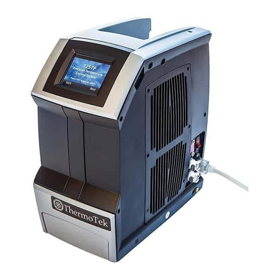
Page 8: Device I Llustration
Device I llustration 8 ... -
Page 9: Setting U P T He T 257P T Emperature C Ontrol S Ystem
Chiller w etted p ath c omponent l ist. 3. Turn ON the T257P Chiller. The power switch is located on the right side of the device, ... - Page 10 6. Open t he r eservoir a nd a dd a dditional f luid a s n eeded. C lose t he c ap s ecurely t o t he r eservoir. 7.
-
Page 11: Run M Ode O Perating P Rocedures
i s n ear a mbient t he f ans w ill e nter t he i dle s tate. 3. To Start the T257P Chiller, press the “Start” button. This will display the RUN Mode screen ... -
Page 12: How T O C Hange T He S Et T Emperature
Figure 5 -‐2: S TANDBY M ode S creen How t o C hange t he S et T emperature 1. From t he R UN M ode S creen, p ress t he “ SetTemp” b utton o n t he s creen. 2. -
Page 13: How T O C Hange T He U Ser S Pecified T Emperature A Larm L Imits
How t o C hange t he U ser S pecified T emperature A larm L imits 1. From t he R UN M ode s creen, p ress t he N ext b utton. 2. -
Page 14: How T O C Hange T He P Ump D Rive ( For A Pplicable C Onfigurations)
How t o C hange t he P ump D rive ( for a pplicable c onfigurations) 1. Some T257P Systems are equipped with a variable speed pump. For these models, the option ... - Page 15 T257P s ystem. F rom t his o ne c an v iew a ll t he a vailable t emperatures, T EC d rive ...
-
Page 16: Standby M Ode O Perating P Rocedures
When the T257P Chiller is powered on (AC power), and is in an idle state, it is said to be ... -
Page 17: How T O S Et T He C Om P Ort
How t o S et t he C OM P ort 1. T257P Systems are equipped with alternate communications port that can be selected for ... -
Page 18: How T O C Hange T He F An D Rive
8. If the “Cancel” button is pressed, the new changes are canceled and the previous com port selection w ill s tay a ctive. 9. -
Page 19: Alarm H Istory
If t he s election i s A UTO, t he s ystem w ill a utomatically c ontrol t he f an s peed b y i ncreasing o r l owering the ... -
Page 20: Checking T He C Oolant L Evel
1. It is highly recommended the fluid contained within the application also be flushed when the T257P C hiller c oolant i s c hanged. 2. Follow a pplication g uidelines f or f lushing p rocedure. ... -
Page 21: Cleaning T He E Xterior O F T He T 257P S Ystem
Cleaning t he E xterior o f t he T 257P S ystem Caution: W hen c learing t he T 257P s ystem, m ake s ure y ou f ollow t he c aution s tatements: ... -
Page 22: Storing T He T 257P S Ystem
Storing t he T 257P S ystem For l ong-‐term s torage o f t he T 257P s ystem, f ollow t hese s teps: 1. -
Page 23: Alarm M Essages
LARM ESSAGES Alarm M essage Alarm D escription If the coolant level in the reservoir drops below the level sensor activation limit for 5 seconds, the device will issue this alarm. ... - Page 24 s ervice f or f urther a ssistance. If the T257P alarm monitoring subsystem detects an internal failure, i t w ill i ssue a c ritical a larm c alled s ystem e rror ( SYS E RR) ...
- Page 25 CCESSORIES EPLACEMENT ARTS The f ollowing a ccessories m ay b e p urchased f rom T hermoTek t o b e u sed w ith t he T 257P s ystem Power ...
-
Page 26: Technical Specifications
ECHNICAL PECIFICATIONS 10.1 T257P S ystem T echnical S pecification 13.2”H x 1 2.00”D x 6 .6”W Device D imensions: [335mmH x 3 05mmD x 1 67mmW] ... -
Page 27: T257P S Ystem P Erformance
10.2 T257P S ystem P erformance Note: 27 ... -
Page 28: T257P C Ommunication P Rotocol
T257P C ommunication P rotocol The T257P Communication protocol is available from ThermoTek Inc upon request. TTK Serial Communication P rotocol ( Document P N: 0 P1GTTKC0M-‐3) i s t he l atest i mplementation t o a ddress t he ... -
Page 29: T257P S Ystem W Etted P Ath M Aterials
10.6 T257P System – Guidance and Manufacture’s Declaration – Electromagnetic Emissions This device has been tested and found to comply with the limits for Electrical equipment for ... - Page 30 • Connect the equipment into an outlet or circuit different from the one where the other device(s) a re c onnected. • Connect an external 20 AWG ground wire from the eqi-‐potential ground tab on the right side of ...
-
Page 31: Warranty
ARRANTY Limited W arranty T erms: T hermoTek, I nc. ( “ThermoTek”) w arrants t o t he i mmediate p urchaser f rom ThermoTek or an immediate purchaser of an unused unit from an authorized distributor of ... - Page 32 DISCLAIMER A ND L imitation o f L iability: t he f oregoing s ets f orth t hermotek’s o nly o bligations a nd t he exclusive claim and remedy against thermotek, regardless of whether such claims are based on ...
- Page 33 33 ...
- Page 34 PN: 0 P1D257MEN R ev: X 1 [ 08/2016] 0P1D257MEN-X1 1200 L akeside P arkway, # 200 Flower ...
Need help?
Do you have a question about the T257P and is the answer not in the manual?
Questions and answers