Advertisement
Quick Links
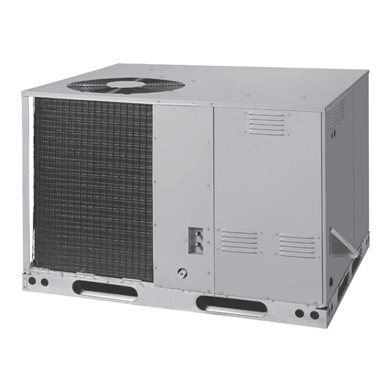
Installer's Guide
Ultra-Low NOx Series
Single Packaged Gas Heating/Electric Cooling
13.4 SEER 2 / 81% AFUE, 2 - 5 Ton Units
Models:
4YCL4024B1055A
4YCL4030B1070A
4YCL4036B1070A
4YCL4042B1100A
4YCL4048B1100A
4YCL4060B1100A
Only qualified personnel should install and service the equipment. The installation, starting up, and servicing of heating, ventilating, and air-conditioning
equipment can be hazardous and requires specific knowledge and training. Improperly installed, adjusted or altered equipment by an unqualified person
could result in death or serious injury. When working on the equipment, observe all precautions in the literature and on the tags, stickers, and labels that
are attached to the equipment.
June 2024
N N o o t t e e : : "Graphics in this document are for representation only. Actual model
may differ in appearance."
S S AFETY WARNING
18-EB42D1-1B-EN
Advertisement

Related Manuals for Trane 4YCL4024B1055A


Summary of Contents for Trane 4YCL4024B1055A
- Page 1 Installer’s Guide Ultra-Low NOx Series Single Packaged Gas Heating/Electric Cooling 13.4 SEER 2 / 81% AFUE, 2 - 5 Ton Units Models: 4YCL4024B1055A 4YCL4030B1070A 4YCL4036B1070A 4YCL4042B1100A 4YCL4048B1100A 4YCL4060B1100A N N o o t t e e : : “Graphics in this document are for representation only. Actual model may differ in appearance.”...
- Page 2 This product complies with SJVAPCD 4905 and SCAQMD 1111 with NOx levels below 14ng/J when operated on natural gas. WARNING FIRE OR EXPLOSION HAZARD Failure to follow safety warnings exactly could result in serious injury, death, or property damage. – Do not store or use gasoline or other flammable vapors and liquids in the vicinity of this or any other appliance.
- Page 3 TABLE OF CONTENTS IMPORTANT SAFETY INFORMATION ......3 START UP & ADJUSTMENTS ........13 Pre-Start Check List ............13 REQUIREMENTS & CODES ........... 4 Start-Up Procedure ............13 Air Circulation ............. 13 GENERAL INFORMATION ..........5 System Cooling ............13 Before you install this unit ..........
- Page 4 IMPORTANT SAFETY INFORMATION WARNING: Please read all instructions before servicing this equipment. Pay attention to all safety warnings and any other special PROPOSITION 65 WARNING: This product contains notes highlighted in the manual. Safety markings are used fiberglass wool, a product known to the state of frequently throughout this manual to designate a degree or California to cause cancer.
- Page 5 Duct Systems REQUIREMENTS & CODES • US and CANADA: Air Conditioning Contractors Association • This equipment must be installed in accordance with (ACCA) Manual D, Sheet Metal and Air Conditioning instructions outlined in this manual, all applicable local Contractors National Association (SMACNA), or American building codes, and the current revision of the National Society of Heating, Refrigeration, and Air Conditioning Fuel Gas Code (NFPA54/ANSI Z223.1) or the Natural...
- Page 6 GENERAL INFORMATION • Overhead obstructions, poorly ventilated areas, and areas subject to accumulation of debris should be avoided. Do not This single package gas heating / electric cooling unit is place the unit in a confined space or recessed area where designed only for outdoor rooftop or ground level slab discharge air from the unit to re-circulate into the condenser installations and can be readily connected to the high static duct...
- Page 7 COMBUSTION AIR & VENTING REQUIREMENTS General Information WARNING: WARNING: CARBON MONOXIDE POISONING HAZARD Installation methods other than those described in Failure to follow the steps outlined below for the following sections must comply with the National each appliance connected to the venting system Fuel Gas Code and all applicable local codes for being placed into operation could result in carbon providing sufficient combustion air to the unit.
- Page 8 Figure 2 shows the proper installation of the vent cover CIRCULATING AIR SUPPLY assembly over the vent outlet on the exterior of the corner panel. The fasteners used to secure the vent cover assembly WARNING: have been included in the owner’s package. The following list summarizes the requirements for the location of the vent Products of combustion must not be allowed to system termination:...
- Page 9 Air Filter Requirements Unconditioned Spaces An air filter is not supplied with this package unit as shipped All duct work passing through unconditioned space must from the factory. The installer must provide a high velocity be properly insulated to minimize duct losses and prevent filter that is appropriately sized to the return air duct opening condensation.
- Page 10 UNIT INSTALLATION the unit’s weight. The slab height must be a minimum of 2” (5cm) above grade and with adequate drainage. See Figure Packaging Removal 4 (page 10). Remove the shipping carton and User’s Manual from the • Remove and discard the horizontal Supply and Return duct equipment.
- Page 11 ELECTRICAL WIRING WARNING: ELECTRICAL SHOCK, FIRE OR EXPLOSION HAZARD Failure to follow safety warnings exactly could result in serious injury, death, or property damage. Improper servicing could result in dangerous operation, serious injury, death or property damage. • Before servicing, disconnect all electrical power to furnace.
- Page 12 • An electrical disconnect must be located within sight sunlight, or lighting fixtures, and convective heat from warm of and readily accessible to the unit. This switch shall be air registers or electrical appliances. Refer to the thermostat capable of electrically de-energizing the outdoor unit. See manufacturer’s instruction sheet for detailed mounting unit data label for proper incoming field wiring.
- Page 13 Humidifier This unit only has right side gas entry. When connecting the The furnace control board provides output terminals for gas, provide clearance between the gas supply line and the an optional humidifier (HUM) that can be installed on your entry hole in the unit’s casing to avoid unwanted noise and/ system.
- Page 14 Shut-Off Valve with 1 /8 NPT plugged tap NOTE: Some utilities require Shut-Off Valve to be 4 to 5 feet above floor Dripleg Automatic Gas Valve (with manual shut-off) Ground Joint Union Figure 7. Typical Gas Hookup - Right Side Entry Verify that the gas line has been purged and all connections To derate the furnace requires knowing the heating value of are leak tight.
- Page 15 System Heating 7. Adjust the manifold pressure if necessary. See Manifold 1. Set the thermostat to the lowest setting. Pressure Adjustment below. For additional information about 2. Follow the procedures given on the operating instruction elevations above 2,000 feet, see page label, this manual or attached inside the louvered control Manifold Pressure Adjustment...
- Page 16 3. After validating the flame, change the thermostat setting to Cooling Cycle below room temperature. 1. The thermostat calls for cooling by energizing the Y & G 4. Verify the burner flame is completely extinguished. terminal with 24VAC. 5. Replace the burner compartment door. 2.
- Page 17 • Inspect, clean or replace air filters at the beginning of each 7. Lift the assembly and bracket straight up out of the burner box heating and cooling season, or more frequently if required. and off the HX panel. NOTE: Use of a flat blade screwdriver Refer to Table 1 (page 8) for recommended external...
- Page 18 TROUBLESHOOTING DIAGNOSTIC DESCRIPTION GREEN LED RED LED If the unit does not operate in the cooling mode, check the Control Fault (No Power) following: • Is the thermostat operating properly? L1/Neutral Polarity Fault Flash Flash • Are the blower compartment doors in place? 1 Hour Lockout Alternating Flash •...
- Page 19 7.29 4.07 47.42 Figure 10. Unit Dimensions CENTER OF GRAVITY HEIGHT IN INCHES (C) MODEL UNIT SHIPPING NUMBER WEIGHT WEIGHT WITH BASE RAILS WITHOUT BASE RAILS 4YCL4024B1055A 26.5 26.5 35.0 31.3 4YCL4030B1070A 26.0 26.5 35.0 31.3 4YCL4036B1070A 26.5 26.5 35.0 31.3...
- Page 20 (ACFM) (ACFM) (ACFM) (ACFM) (ACFM) RISE RISE RISE RISE RISE RISE RISE RISE Tap T1** 996 Tap T2 4YCL4024B1055A 35-65 Tap T3 Tap T4 Tap T5 Tap T1 1243 1158 1076 Tap T2** 1393 1310 1255 1172 1099 1021 4YCL4030B1070A...
- Page 21 EXTERNAL STATIC PRESSURE DROP - INCHES WATER COLUMN MODEL MOTOR NUMBER SCFM SCFM SCFM SCFM SCFM SCFM SCFM SCFM Tap T1 Tap T2 4YCL4024B1055A Tap T3 1112 1050 Tap T4* 1160 1105 1053 Tap T5 1472 1411 1350 1295 1228...
- Page 22 Gas Information CAPACITY OF BLACK IRON GAS PIPE (CU. FT. PER HOUR) FOR NATURAL GAS (SPECIFIC GRAVITY - 0.60) LENGTH OF PIPE RUN (FEET) NOMINAL PIPE DIAMETER (IN.) 1 1/4 1,050 1 1/2 1,600 1,100 Input To Furnace (Btu/hr) Cubic Feet Per Hour Required = Heating Value of Gas (Btu/Cu.
- Page 23 FOR YOUR SAFETY READ BEFORE OPERATING WARNING: If you do not follow these instructions exactly, a fire or explosion may result causing property damage, personal injury, or loss of life. A. This appliance does not have a pilot. It is equipped with an ignition device which automatically lights the burner.
- Page 24 Wiring Diagram & Electrical Data HIGH XFMR R C Y G W Figure 12. Wiring Diagram for 230V / 60 Hz Unit...
- Page 25 Wiring Diagram & Electrical Data HIGH XFMR R C Y G W Figure 13. Wiring Diagram for 230V / 60 Hz Unit with ECM Outdoor Motor...
- Page 26 HEATING NOMINAL VOLTAGE RANGE COMPRESSOR INDUCER MINIMUM MAXIMUM MODEL BLOWER INPUT ELECTRICAL MOTOR CIRCUIT OVER-CURRENT NUMBER AMPS AMPS (BTUH) SUPPLY MIN. MAX. AMPS AMPACITY PROTECTION 024K 55,000 230-60-1 12.8 58.3 20.8 030K 70,000 230-60-1 14.1 1.46 24.5 036K 70,000 230-60-1 16.7 1.46 27.7...
- Page 27 FURNACE COMPONENTS The descriptions below are various functional components that affect the operation and shutting down of this furnace. Some of these components and their locations are shown in Figure 14. If any component of the furnace must be replaced, use only factory authorized replacement parts specified in the Replacement Parts List.
- Page 28 INSTALLATION CHECKLIST GAS SYSTEM INSTALLATION ADDRESS: Natural Gas Type: (circle one) Propane CITY: STATE: Gas pipe connections leak-tested? UNIT MODEL # Gas Line Pressure (in - W.C.): Is there adequate fresh air supply UNIT SERIAL # for combustion and ventilation? Unit Installed Minimum clearances Installation Altitude (FT.): Figure 1 (page...
- Page 30 About Trane and American Standard Heating and Air Conditioning Trane and American Standard create comfortable, energy efficient indoor environments for residential applications. For more information, please visit www.trane.com or www.americanstandardair.com. The manufacturer has a policy of continuous data improvement and it reserves the right to change design and specifications without notice. We are committed to using environmentally conscious print practices.
Need help?
Do you have a question about the 4YCL4024B1055A and is the answer not in the manual?
Questions and answers