Advertisement
Available languages
Available languages
Quick Links
WÜRTH Industrie Service
ORSY
®
Betriebsanleitung zum Master- und Satellitenmodul
ORSY
®
Operating instructions for the Master and Satellite module
Art. 0961 091 600, 0961 091 601, 0961 091 630, 0961 091 631
mat RT
mat RT
Originalbetriebsanleitung
Translation of the original operating instructions
Advertisement

Related Manuals for Würth ORSY mat RT

Summary of Contents for Würth ORSY mat RT
- Page 1 WÜRTH Industrie Service ORSY mat RT ® Betriebsanleitung zum Master- und Satellitenmodul ORSY mat RT ® Operating instructions for the Master and Satellite module Art. 0961 091 600, 0961 091 601, 0961 091 630, 0961 091 631 Originalbetriebsanleitung Translation of the original operating instructions...
- Page 2 ...... 3 – 26 ...... 27 – 50...
- Page 3 INHALTSVERZEICHNIS Allgemein . . . . . . . . . . . . . . . . . . . . . . . . . . . . . . . . . . . . . . . . . . . . . . . . . . . . . . . . . . . . . . . . 1 .1 Einleitung .
- Page 4 1 ALLGEMEIN 1.1 Einleitung 1.1.1 Copyright © Würth Industrie Service GmbH & Co . KG Diese Dokumentation ist urheberrechtlich geschützt . Die dadurch begründeten Rechte, insbesondere die der Übersetzung, des Nachdrucks, der Entnahme von Abbildungen, der Funksendung, der Wiedergabe auf fotomechanischem oder ähnlichem Wege und der Speicherung in Datenverarbeitungsanlagen bleiben, auch bei nur auszugsweiser Verwendung, vorbehalten .
- Page 5 1.2 Kundendienst Beim Auftreten von Störungen, die Sie selbst nicht beseitigen können, hilft Ihnen gern unser Kundendienst weiter . Dabei ist die Angabe der Automaten-ID aus dem Service-Center, der Seriennummer des Moduls und des Softwarestandes relevant . Für Mängelansprüche sind diese Angaben zwingend erforderlich . 1.3 Typenschild Das Typenschild befindet sich auf der hinteren Gehäuseaußenseite links oben.
- Page 6 Weitere Typenschilder: Vollständiges Identifikationsschild Identifizierungsschild Sicherheitsaufkleber zur Warnung vor Drehvorrichtungen Sicherheitsaufkleber zur Warnung vor heißen Oberflächen Sicherheitsaufkleber zur Warnung vor Stromspannung Beseitigung in Übereinstimmung mit WEEE, nach der Umsetzung in einzelstaatliches Recht . (LED-BELEUCHTUNG) LASERSTRAHLUNG – BITTE NICHT LÄNGERE ZEIT IN DEN STRAHL BLICKEN – LASERPRODUKT DER KLASSE 2 Das vollständige Identifikationsschild "A"...
- Page 7 1.4 Sicherheitshinweise Der Automat ist nach dem aktuellen Stand der Technik gebaut und betriebssicher . Dieser ist ausschließlich seinem eigentlichen Zweck einzusetzen . Allgemeines Gebotssymbol ACHTUNG! Elektrostatisch empfindliche Bauteile (ESD) Beschädigungsgefahr der Bauteile! Leiterplatten und Pins auf der Steuerung nicht berühren! 1.5 Hinweise vor der Inbetriebnahme •...
- Page 8 2 BESTIMMUNGSGEMÄSSE VERWENDUNG 2.1 Einsatzgebiete und Einsatzgrenzen 1 . Der Verkaufsautomat ist bestimmt für den Einsatz in gewerblicher Umgebung für die Warenentnahme durch Endverbraucher . Es liegt in der Verantwortung des Betreibers, den Zugang und die Umgebung so zu gestalten und auszuleuchten, dass Bedienpersonen und Endverbraucher gefahrenlos Zutritt haben . 2 .
- Page 9 Bestandteilen, müssen andere bei der Herstellerfirma bestellte Originalschilder an ihre Stelle treten, wobei sie genau in der hier beschriebenen Position anzubringen sind . Es soll daran erinnert werden, dass ein vorsichtiger Techniker in stabilem psychischem Zustand die beste Versicherung gegen jede Art von Unfall bietet. 2.2 Umgebungsbedingungen Ein Betrieb ist nur im Innenbereich zulässig .
- Page 10 3 LIEFERUMFANG Master Modul Pos. Beschreibung Stückzahl Master Modul inkl . Steuerung Barcode-Scanner inkl . USB-Kabel Barcode Scanner Schale Schlüssel für Korpus-Türe Mobilfunk Antenne Kaltgeräte Stecker Satelliten Modul Pos. Beschreibung Stückzahl Satelliten Modul Schlüssel für Korpus-Türe CAN-Kabel (bereits angeschlossen) Kaltgeräte Stecker 4 INSTALLATION Die Installation und die anschließenden Wartungsarbeiten müssen durch geschultes Fachpersonal erfolgen, das hinsichtlich der Sicherheit mit dem Gerät vertraut ist .
- Page 11 Der Hersteller lehnt jede Verantwortung für Schäden ab, die auf die Missachtung der vorstehend erläuterten Vorsichtsmaßnahmen zurückzuführen sind. 4.1 Auspacken des Gerätes Nach Entfernen der Verpackung das Gerät auf Unversehrtheit überprüfen . Im Zweifel das Gerät nicht ver- wenden . Die Verpackungsmaterialien müssen durch autorisierte Fachbetriebe entsorgt und weiterverwertet werden .
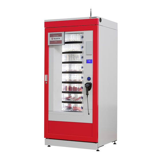
- Page 12 5 VORSTELLUNG Der ORSY mat ist ein modular erweiterbares Automatensystem mit elektronisch verriegelbaren Verkaufsklap- ® pen zur Lagerung von Werkzeugen und Verbrauchsmaterial aller Art. Durch die flexible Zusammenstellung von anderen Automatenmodulen und Facheinteilungen können spezifische Bedarfe an Material für den Endkunden verwaltet werden . Die Bedienung über die Automatensoftware stellt eine kontrollierte Lagerung und Ausgabe der Ware sicher .
- Page 13 5.1.2 Satellitenmodul Das Satellitenmodul unterscheidet sich zu dem Mastermodul hauptsächlich in der fehlenden Display- Steuerung, des Routers und des Barcode-Scanners . Alle weiteren Merkmale des Trommelautomaten sind identisch und nicht nochmals in der Zeichnung beschrieben . Kabelauslassdose (CAN-Kommunikation Satellit) Verstellbare Füße...
- Page 14 6 AUTOMATENSTEUERUNG ACHTUNG! Elektrostatisch empfindliche Bauteile (ESD) Beschädigungsgefahr der Bauteile! Leiterplatten und Pins auf der Steuerung nicht berühren! Der Automat wird ausschließlich über das vordere Display bedient . Die Freigabe der Verkaufsklappen kann nur über eine ordnungsgemäße Abfolge in der Automatensoftware geschehen . 6.1 Befüllung mit Ware Der nachfolgende Einlagerungsprozess wird exemplarisch dargestellt: Nachdem die Kunden-Konfiguratio- nen durchgeführt worden sind und die Verkaufsfächer mit einem IST-Wert von 0 belegt sind, wird im Zuge...
- Page 15 6.2 Schema für Verkaufsablauf Nachfolgend wird der Verkaufsprozess schematisch über das Touch-Display dargestellt . Der Zugriff auf entsprechende Menüpunkte in der Software kann nur unter freigeschalteten Benutzerrechten erfolgen: Barcode Anmeldung RFID Pincode Auswahl Entnahmemenü Auswahl des Artikels Bestätigung des Artikels Trommel dreht sich bis zur gewünschten Position.
- Page 16 6.3 Schema für Einlagerungsablauf Nachfolgend wird der Einlagerungsprozess schematisch über das Touch-Display dargestellt . Der Zugriff auf entsprechende Menüpunkte in der Software kann nur unter freigeschalteten Benutzerrechten erfolgen: Barcode Anmeldung RFID Pincode Auswahl Menüpunkt Einlagerung Anwahl Einlagerungsartikel Bestätigung des Artikels Trommel Nummer wird im kleinen Display angezeigt.
- Page 17 7 PROGRAMMIERUNG FAS-STEUERUNG Die äußere und innere Tür öffnen . Das Flachbandkabel zwischen FAS-Steuerung und CAN-Kopf Modul abstecken . Nun den Modus-Knopf (TEST) etwa 2 Sekunden lang gedrückt halten, bis auf der zweiten Dis- playzeile die Meldung "Befehl 00" erscheint und der Summer einen langen Ton von sich gibt. In der ersten Zeile des Displays erscheint dagegen die Anzeige, dass sich der Automat im "Programmier- modus"...
- Page 18 Befehl Einstellung der Fächer Anzahl auf Trommelebene Nummer 5 Befehl Einstellung der Fächer Anzahl auf Trommelebene Nummer 6 Befehl Einstellung der Fächer Anzahl auf Trommelebene Nummer 7 Befehl Einstellung der Fächer Anzahl auf Trommelebene Nummer 8 Befehl Baudrate = muss auf 115200 eingestellt sein 7.3 Befehl 01 Maschinentest Dieser Test dient zur Ausführung eines Maschinenfunktionstests .
- Page 19 ACHTUNG: Während dieser Phase sind mechanische Teile in Bewegung . Diese Funktion nicht ohne geschultes Personal durchführen . 7.6 Entfernen der Trommeln Die Trommel wird wie folgt aus dem Kasten genommen: Die Haupttür des Automaten öffnen und die Stromversorgung durch Umlegen des Hauptschalters auf Off unterbrechen .
- Page 20 Falls auch der Trommelschlitten entfernt werden muss, ist der Stecker “D” an der linken Seitenwand im Kasten abzuziehen, dann den Feststeller “C” an den Seitenwänden anheben und den Kasten entnehmen . Wiedereinsetzen der Trommel in den Kasten: Zunächst die Trommel mit dem Riemen des Getriebe- motors “A”...
- Page 21 7.7 Nutzraummaße Produktfächer Anzahl der Fächer A (mm) B (mm) H (mm)
- Page 22 8 ABMESSUNGEN, GEWICHT, ELEKTRISCHER ANSCHLUSS Höhe H = 1830 mm Breite L = 910 mm Tiefe P = 795 mm P1 = 1670 mm Gewicht (ohne Verpackung) 315 kg Nennspannung siehe Typenschild Nennleistung siehe Typenschild Grenzwerte der Umgebungsbedingungen für den Umgebungstemperatur max . 32°C Betrieb Umgebungstemperatur min .
- Page 23 9 SOFTWARE UPDATE Für Software Updates sind die entsprechenden Service-Berechtigungen am Automaten vorausgesetzt . Die Automatensoftware auf dem Mediamodul kann folgendermaßen aktualisiert werden: 1 . Service-Center aufrufen (Web-Browser) 2 . Automatenmodul über die Kundennummer suchen 3 . Gewünschte Software in dem Reiter auswählen 4 .
- Page 24 10 TRANSPORT, LAGERUNG, AUSSERBETRIEBNAHME, ENTSORGUNG 10.1 Transporthinweise • Durch unsachgemäßen Transport kann der Automat beschädigt werden . Bei Transport mit einem Hub- wagen: durch ruckartiges Absenken kann der Automat beschädigt werden . • Lebensgefahr! Durch unsachgemäßen Transport kann der Automat kippen. Bei Transport, sowie Be- und Entladen müssen die folgenden Sicherheitshinweise beachtet werden: •...
- Page 25 Die Verpackungsmaterialien sind wegen des Umweltschutzes nach den geltenden Gesetzesvorschriften zu entsorgen. Den Automaten anheben und dabei darauf achten, dass die Stützfüße aus der Palettenform austreten. 11 INDEX Abmessungen Automatensteuerung Befüllung Einlagerungsprozess Elektrischer Anschluss Entsorgung Gewicht Installation Kundendienst 5 Lagerung Lieferumfang Maschinentest Sicherheitshinweise 7...
- Page 26 12 EU-/EG-KONFORMITÄTSERKLÄRUNG FÜR MASCHINEN...
- Page 27 TABLE OF CONTENT General . . . . . . . . . . . . . . . . . . . . . . . . . . . . . . . . . . . . . . . . . . . . . . . . . . . . . . . . . . . . . . . . . 1 .1 Introduction .
- Page 28 1 GENERAL 1.1 Introduction 1.1.1 Copyright © Würth Industrie Service GmbH & Co . KG This document is copyright-protected . Any rights derived from the copyright, in particular those of transla- tion, reproduction, extraction of illustrations, radio broadcast, photomechanical or similar reproduction and storage in data processing equipment, shall be reserved even for partial use thereof .
- Page 29 1.2 Customer service In the event of incidents that you cannot resolve yourself, our customer service will be happy to help you . Please specify the vending machine ID from service centre, serial number of the module and software version . These details are mandatory for claiming for defects .
- Page 30 Different types of nameplates: Complete identification plate Identification plate Safety label to warn about rotators Safety label to warn about hot surfaces Safety label to warn about voltage Disposal in accordance with WEEE, once adopted in national law . (LED-LIGHTING) LASER RADIATION – PLEASE DO NOT LOOK INTO THE BEAM FOR A LONGER PERIOD OF TIME –...
- Page 31 1.4 Safety instructions The vending machine is built to current state-of-the-art standards and is safe to operate . It is to be used solely for its intended purpose . General mandatory symbol ATTENTION! Electrostatically sensitive components (ESD), risk of damage to the components! Do not touch printed boards and pins on the control! 1.5 Instructions before starting up •...
- Page 32 2 INTENDED USE 2.1 Areas and limits of applications 1 . The vending machine is intended for use in a commercial environment for the withdrawal of goods by end users . The operator is responsible for designing and lighting the access and the surrounding area in such a way that the operators and end users have safe access .
- Page 33 It is important to remember that a cautious technician in a stable state of mind offers best insurance against any kind of accident. 2.2 Ambient conditions Operation is permitted only in indoor areas . The machine should be protected from moisture, rain or splash- ing water .
- Page 34 3 SCOPE OF DELIVERY Master module Item Description Quantity Master module incl . control Barcode scanner incl . USB cable Barcode scanner jacket Key for body doors Mobile radio antenna IEC connector Satellite module Item Description Quantity Satellite module Key for body doors CAN cable (already connected) IEC connector 4 INSTALLATION...
- Page 35 The manufacturer is not liable for any damages, which can be attributed to the failure to observe precautionary measures explained above. 4.1 Unpacking the machine After removing the packaging, check whether the machine is intact . In case of any doubt, do not use the machine .
- Page 36 5 INTRODUCTION ORSY mat is a modular and expandable system with electronically controlled drums and flaps for selling ® and storing all types of tools and consumables. The specific requirements of material can be managed for end customers by flexibly combining other vending machine modules and partitions. The operation via vending machine software ensures controlled storage and output of goods .
- Page 37 5.1.2 Satellite module The satellite module differs from the master module mainly in the missing display control, router and barcode scanner . All other features of rotating vending machines are identical and not described again in the design . Cable outlet (CAN satellite communication) Adjustable feet...
- Page 38 6 VENDING MACHINE CONTROL ATTENTION! Electrostatic sensitive components (ESD), risk of damage to the components! Do not touch printed circuit boards and pins on the control! The vending machine is operated via front display only. The sales flaps can only be released via a proper sequence in the vending machine software .
- Page 39 6.2 Flowchart for sales process We have schematically displayed the sales process via touch display . The relevant menu options in the software can only be accessed with enabled user rights: Barcode Login RFID Pincode Select menu button withdrawal Select article Confirm article Drum rotates to the desired...
- Page 40 6.3 Flowchart for storage process We have schematically displayed the storage process via touch display . The relevant menu options in the software can only be accessed with enabled user rights: Barcode Login RFID Pincode Select menu button storage Select article Confirm article Drum number is shown in the...
- Page 41 7 PROGRAMMING OF FAS CONTROL Open the outer and inner door . Disconnect the ribbon cable between FAS control and CAN head module . Now press and hold the mode button (TEST) for around 2 seconds till the message “command 00” appears on the second display line and the buzzer makes a long sound .
- Page 42 Command Setting the number of compartments at drum-level number 7 Command Setting the number of compartments at drum-level number 8 Command Baud rate = should be set to 115200 7.3 Command 01 machine test This test is used to carry out machine function test . First type 01 and then press ENTER . The display shows “Please enter the desired test …1 or 2 or 3”.
- Page 43 ATTENTION: During this phase, the mechanical parts are in motion . Do not carry out this function without a trained personnel .
- Page 44 7.6 Removing the drums The drum is taken out of the case as follows: Open the main door of the vending machine and disconnect the power supply by flipping the main switch to off . Remove the drum sled against the impact of the positioning spring . Pull the drum sled till the locking device .
- Page 45 7.7 Usable space dimensions of the product compartments Number of A (mm) B (mm) H (mm) compartments...
- Page 46 8 DIMENSIONS, WEIGHT, ELECTRICAL CONNECTION Height H = 1830 mm Width L = 910 mm Depth P = 795 mm P1 = 1670 mm Weight (without packaging) 315 kg Nominal voltage See name plate Nominal capacity See name plate Thresholds of ambient conditions for the operation Ambient temperature max .
- Page 47 9 SOFTWARE UPDATE The relevant service authorizations for vending machines are required for software updates . The vending machine software on the media module can be updated as follows: 1 . Select service center (web browser) 2 . Search for vending machine module using the customer number 3 .
- Page 48 10 TRANSPORT, STORAGE, SHUTTING DOWN, DISPOSAL 10.1 Transport guidelines • The vending machine can be damaged due to improper transport . In case of transport with pallet truck: sudden, jerky lowering can damage the vending machine. • Danger of death! The vending machine can tip due to improper transport. The following safety instructions should be adhered while transporting as well as loading and unloading: •...
- Page 49 The packaging materials are to be disposed off according to the valid legal regulations for the sake of the environment. Lift the vending machine and make sure that the support feet come out of the pallet form. 11 INDEX Customer service Dimensions Disposal Electrical connection...
- Page 50 12 EU/EG DECLARATION OF CONFORMITY FOR MACHINES...
- Page 52 Würth Industrie Service GmbH & Co . KG © Würth Industrie Service GmbH & Co . KG Nachdruck, auch auszugsweise, nur mit Genehmigung . Industriepark Würth, Drillberg Gedruckt in Deutschland . MW – SF/CF – PDF – 1 – 01/22 – DBRO600069 97980 Bad Mergentheim Alle Rechte vorbehalten .
Need help?
Do you have a question about the ORSY mat RT and is the answer not in the manual?
Questions and answers