Advertisement
Quick Links
Advertisement

Related Manuals for Aliaxis FRIATEC FRIAMAT 6 110V


Summary of Contents for Aliaxis FRIATEC FRIAMAT 6 110V
- Page 1 Operating instructions FRIAMAT 6 110V...
- Page 2 Table of Content About this document ..................... 7 1.1. Objective and target group of these instructions ..........7 1.2. About these operating instructions ..............7 1.3. Symbols used ...................... 7 1.4. Representation for the menu navigation ..............8 1.5. Applicable relevant documents ................8 1.6.
- Page 3 3.3. Function keys .....................15 3.4. Display ....................... 16 3.4.1. Display structure ................16 3.4.2. Function key symbols ................ 17 3.4.3. Function status symbols ..............18 3.5. Rating plate ......................18 3.6. Reading device ....................19 3.6.1. Scanner ....................19 3.7. USB data interface with protective cap ..............19 3.8.
- Page 4 Menu operation ......................28 8.1. Operate menu ....................28 8.1.1. Entering via the virtual keyboard or numeric keypad ......28 8.1.2. Acquiring entries or settings ...............28 8.2. Acquire device settings ..................28 8.2.1. Set the date and time .................28 8.2.2. Select the system language ...............28 8.2.3.
- Page 5 8.5. Manage capture data ..................32 8.5.1. Transmit data ..................32 8.5.2. Delete data ..................32 8.6. Reading in an operator pass ................33 Fusion procedure ......................33 9.1. Read in barcode ....................33 9.1.1. Utilise the reading device ..............33 9.1.1.1. Utilising the scanner ............33 9.1.2.
- Page 6 12.2. Maintenance, testing and inspection intervals ........... 44 12.3. Warranty ......................45 Disposal ........................45 Technical Data ......................45 Authorised service stations ..................47...
- Page 7 1. About this document 1.1. Objective and target group of these instructions These instructions describe all the necessary work steps, measures and precautions in order to ensure safe and professional handling of the product. These instructions are intended for the following target group: ▪ People who will transport, commission and operate the product Operators and/or owners ▪...
- Page 8 CAUTION This warning describes a possible imminent danger. ⯈ Failure to observe it may result in minor to moderate injuries. HINT This warning describes a danger that may result in damage to property. ⯈ Measures to avoid damage to property are described here. INFO This note provides information on the following topics: ▪...
- Page 9 The technical information contained in these operating instructions is reviewed regularly to make sure it is up to date. The date of the last revision is specified on the document. Updated instructions are available online at http://www.aliaxis.de/en/services/downloads 2. Safety The FRIAMAT 6 110V fusion unit corresponds to the state of the art and is built according ...
- Page 10 ▪ 26/40-digit (according to ISO 12176-4) 30-digit (according to ISO 12176-3) ▪ The FRIAMAT 6 110V fusion unit has been designed for industrial applications. This comprises the voltage power supply with generators and standard mains voltage. Designated intended use also includes compliance with the following instructions: Notes and information in these operating instructions ▪...
- Page 11 2.4. Structural alterations to the product and spare parts Conversions, alterations and modifications to the FRIAMAT 6 110V fusion unit are not permitted for safety reasons. All warranty claims will become invalid for FRIAMAT 6 110V fusion units whose lead seals have been broken. 2.5. Obligations of the owner ▪ To always ensure that the personnel fulfil the following requirements: ▪ Personnel are trained in the proper use and handling of the device. Personnel have read and understood the instructions and safety information. ▪ Make these instructions available to the personnel. ▪ INFO The FRIAMAT 6 110V fusion unit is not intended for use by persons (including children!) with reduced physical, sensory or mental capabilities, or lack of experience and knowledge, unless they have been given supervision or...
- Page 12 In case of doubt e.g. with new procurement, please contact Aliaxis Deutschland GmbH. 2.11.3. Extension Cables ▪...
- Page 13 Always disconnect the mains cable before executing any repair work or maintenance ▪ work. ▪ Always only have any servicing, maintenance and repairs executed by Aliaxis Deutschland GmbH or authorised service stations. ▪ Only connect the device to the approved operating voltage which is specified on the rating plate.
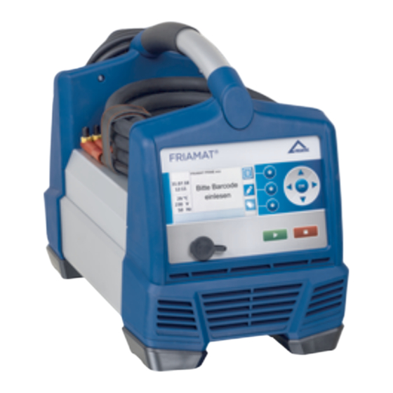
- Page 14 3. Product description 3.1. Function description The fitting parameters will be transmitted to the fusion unit by reading the barcode in with a barcode scanner. Based on this data, the microprocessor-controlled FRIAMAT 6 110V fusion unit is able to regulate and control the energy metering fully automatically and de- termines the fusion time, taking into account the ambient temperature.
- Page 15 3.3. Function keys Image 2: Description for the operating and control components based on FRIAMAT 6 110V Position Designation Description Function Access to function key symbols which are shown on the keys display Direction Movement of the cursor in the menu in the directions for keys left, right, up, down OK key Confirms a procedure START key Starts the fusion procedure Confirms the messages which are shown on the display...
- Page 16 3.4. Display 3.4.1. Display structure Image 3: Description for the display based on the FRIAMAT 6 110V Position Designation Description Function status ▪ Functions which are available at this point in time. symbols Notice for next maintenance. ▪ Display for ▪ Important environmental information (date, time, environmental ambient temperature, voltage and frequency). information Number of This count number corresponds to the number of...
- Page 17 3.4.2. Function key symbols Symbol Designation Description Menu Call up the main menu. Entry input/ Calls up a virtual keyboard. emergency Manual input possibility for a barcode e.g. when this input cannot be read. ID data For calling up the input mask for ID data, picking and sorting number, seam number and GPS data.
- Page 18 3.4.3. Function status symbols Symbol Description Documentation is switched on. Entry for seam number is possible. Traceability barcodes can be entered. Entry for pipe number is possible. Entry for pipe length is possible. USB stick is connected. Maintenance appointment: Notice for the next maintenance due (in days). ®...
- Page 19 ▪ Unique device number 3.6. Reading device 3.6.1. Scanner The mini-scanner reads in 1D barcodes. The 1D/2D scanner (optional) reads in 1D barcodes and 2D barcodes according to ISO 12176-5. 3.7. USB data interface with protective cap The USB data interface serves as a service interface for software updates and for data transfer with the FRIAMAT fusion unit.
- Page 20 ▪ During a fusion Between fusions ▪ ▪ After a fusion Always leave the device switched on after a fusion so that the fan can reduce the temperature of the fusion unit. This applies in particular to series fusions, machining or processing of fittings with high power requirements.
- Page 21 After registration of the device in the "FRIAMAT Software Update" module, update notifications and additional, ongoing device-specific information and innovations for the registered FRIAMAT fusion units will be sent by email from Aliaxis Deutschland and its affiliated companies to the email address which are stored in the user account of the...
- Page 22 The user can download software updates and install them on the device themself (refer to Chapter 9.5. Install software update). 3.15. Data transfer 3.15.1. Output Formats The following output formats are available: ▪ JSON ▪ 3.15.2. Designating the transferred data Designating the subdirectories The transferred data will be created in subdirectories on the USB stick according to the following pattern: F+Device number Example: FR 24 3 0123...
- Page 23 Menu Level 1 Level 2 Level 3 Reference Main menu Basic settings Documentation Switch on/switch off documentation Date and time Set the date and time * System language * Select the system language Protocol language Select protocol language Volume Set signal tone volume ®...
- Page 24 Menu Level 1 Level 2 Level 3 Reference GPS data GPS data Data Transmit Transmit data Delete Delete data Information View device information Device information Device number SW HMI SW PU Maintenance date Device function Licenses Menu emergency entry Enter barcode digits manually (emergency entry) ID data menu...
- Page 25 ▪ An unfavourable machining or processing situation is e.g. the fusion cable end piece is located in the blazing sun and the fitting is located in the shade. Input voltage corresponds to the input voltage range for which the device is designed ▪...
- Page 26 With generator operation: Always observe the safety precautions for generation operation (refer to Chapter 2.11.2. Generator operation). Start up the generator and allow it to warm up for 30 seconds. If necessary, adjust the idling voltage and limit it to the voltage which is specified in the technical data.
- Page 27 Using the entered personal data The personal email address, which has been entered in the activation dialogue of the device, will be utilised and stored by Aliaxis Deutschland in order to send information about the availability of new software updates and device updates to the owner of the email address easily and quickly.
- Page 28 INFO When changing owners ▪ Always inform the new owner about the update options and the use of the 'FRIAMAT Software Update' module in the customer portal at www.aliaxis.de/ ▪ Always inform Aliaxis Deutschland about the change of ownership. ▪ Resetting to factory or default settings (refer to Chapter 8.2.4. Resetting the device to factory settings) and deleting fusion data when necessary.
- Page 29 8.2.3. Set signal tone volume Call up the menu item: Main menu > basic setting > volume Set signal tone volume to loud or quiet. 8.2.4. Resetting the device to factory settings Call up the menu item: Main menu > basic setting > factory settings Reset the device to the factory settings. 8.2.5.
- Page 30 Call up the menu item: ® Main menu > basic setting > Bluetooth ® Bluetooth function switched on or switched off. If the function is switched on, then the following symbol will appear in the display: ▪ 8.3.3. Traceability active Call up the menu item: Main menu >...
- Page 31 8.4.1.2. Pipe length Call up the menu item: Main menu > fusion sequence > traceability > pipe length Switch on or switch off the query for the pipe length for the pipe which is to be fused. If the function is switched on, then the following symbol will appear in the display: ▪...
- Page 32 8.4.3. ID data The request for ID data in the ID data menu and during the fusion process can be defined in the ID data menu item. 8.4.3.1. Sorting and picking number Call up the menu item: Main menu > fusion sequence > ID data > sorting and picking number Switch on or switch off the query for sorting and picking number.
- Page 33 8.6. Reading in an operator pass When an operator pass is initially read in, then all fusions performed from this point on will be saved under the code of the operator pass which has been read in. When another operator pass is read in, then the device switches over accordingly. By reading in the same operator pass again, the device can be subsequently disabled in order to protect it against unauthorised use.
- Page 34 9.1.2. Scan in the barcode with the reading device INFO Utilising a barcode from another type of fitting Fusing aborted or faulty fusing result ▪ Only read in the barcode which is adhered on the fitting. ▪ If the barcode is missing or damaged: Read in the barcode of an identical fitting model (same manufacturer, same batch).
- Page 35 9.2. Executing the fusion procedure 9.2.1. Enter ID data INFO Entering sorting and picking numbers, seam numbers and GPS data is only possible under the following prerequisites: ▪ Documentation is switched on. ▪ Functions for "Sorting and picking number" / "Seam number" / "GPS data" are switched on (refer to Chapter 8.4.3.
- Page 36 INFO Aborting the fusion procedure The fusion procedure can be interrupted at any time by pressing the STOP key. The fusion process can be repeated. ▪ Let the fusion joint cool down. ▪ If necessary, remedy the source of the error. ▪...
- Page 37 Display Procedure “Testing and inspecting” ▪ The ambient temperature will be measured and the resistance of the connected fitting must be tested. ▪ Testing the connected fitting and the FRIAMAT preCHECK function will be executed. ▪ If the test result is positive, then fusion starts automatically.
- Page 38 9.2.5. Conclude the fusion procedure Prerequisite ▪ Fusion procedure is ended. The display shows "Fusion successful" with "Fusion time target" and "Fusion time ▪ actual". Note the fusion parameters on the pipe/fitting in order to prevent double fusions. Confirm the display indication with the OK key (alternatively START key, STOP key). The fusion procedure is concluded.
- Page 39 9.5. Install software update INFO When the update cannot be installed on the device, then immediately contact the authorised service station or the local service partner or Aliaxis Deutschland (refer to Chapter 15. Authorised service stations). Prerequisites A commercially available computer with USB port and Internet access.
- Page 40 ▪ USB stick which is formatted in FAT 32 with up to 256 GB. Call up the customer portal via a browser: www.aliaxis.de/portal Navigate to the "FRIAMAT Software Update” module in the customer portal. Download the update. Every update comprises a data package with several files in which the following...
- Page 41 Should the FRIAMAT fusion unit output an error message or warning that is not listed in the following table and that cannot be explained or remedied despite the plaintext description, contact the service hotline of the Aliaxis Deutschland GmbH, Tel. +49 621 486-1533! Error messages, fault messages or warnings will be shown in the device display.
- Page 42 No. Text in display Meaning / causes Assistance Operating Operating voltage ▪ Inspect voltage and voltage during fusion is connection conditions of the out of range outside the generator permissible range. Extension cable too long or cross-section too small Frequency out of Frequency during ▪...
- Page 43 Voltage ... V; ▪ Re-regulate the generator. Frequency ... Hz ▪ Acknowledge with the STOP button. Maintenance Have the device maintained (Aliaxis Deutschland GmbH date or authorised service station). exceeded FRIAMAT The FRIAMAT preCheck function has been switched off when preCheck...
- Page 44 12. Care and maintenance 12.1. Device maintenance ▪ The fusion unit must be maintained at least once a year by Aliaxis Deutschland GmbH or one of the authorised service stations. According to the international valid standard ISO 12176-2 Plastics pipes and fittings - Equipment for fusion jointing polyethylene systems - Part 2: Electrofusion, in this case Clause 7.1, an electrofusion device must only maintain the required operating accuracy at...
- Page 45 2012/19/EU (WEEE - Waste Electrical Devices and Electronic Equipment). ▪ Always observe additional country- specific provisions, regulations, standards and directives. Possible locations, bodies for proper disposal: Aliaxis Deutschland GmbH ▪ ▪ Authorised service stations 14. Technical Data Technical Data FRIAMAT 6 110V Input voltage range Nominal 95 V – 138 V Frequency range 44 Hz...66 Hz...
- Page 46 Technical Data FRIAMAT 6 110V Fusion cable 4 m with fitting connection plug Ø 4 mm Code type Barcode 128 or 2D Data Matrix (Aztec Format) ▪ according to ASTM F-2897-21 Barcode 2/5 overlapped (interleaved) according ▪ to ANSI HM 10.8 M-1983 and ISO CD 13950 ▪...
- Page 47 15. Authorised service stations Aliaxis Deutschland GmbH FRIATOOLS Steinzeugstraße 50 D-68229 Mannheim, Germany Service Hotline: +49 621 486-1533 Current overview for service stations worlwide: https://www.aliaxis.de/en/services/tools- service ...
- Page 48 Aliaxis Deutschland GmbH Infrastructure Steinzeugstraße 50 68229 Mannheim, Germany T +49 621 486-2238 info.de@aliaxis.com www.aliaxis.de...
Need help?
Do you have a question about the FRIATEC FRIAMAT 6 110V and is the answer not in the manual?
Questions and answers