Advertisement
Quick Links
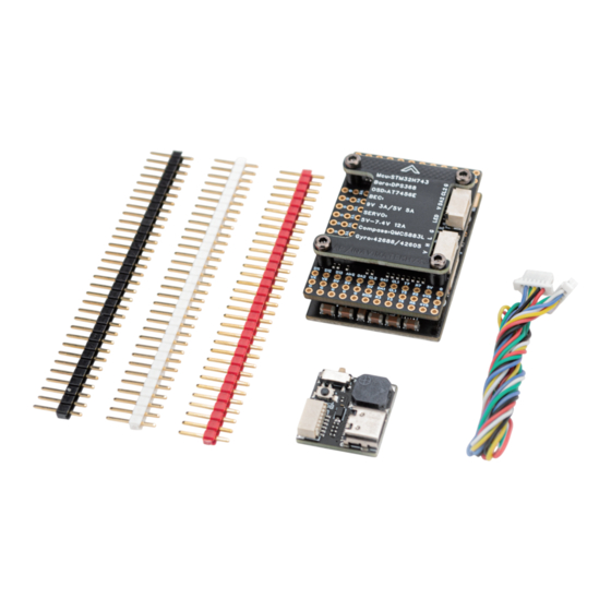
Parameters:
MCU:STM��H���VIH�
●
Gyroscope: ICM-�����-P + ICM-����� dual
●
Barometer: DPS���
●
Compass: QMC����L
●
OSD:Analog/HD OSD
●
�xUARTs, ��xPWMs, �xI�C, �xCAN, �xADC (VLT�, CURR�, ASPD, RSSI),
●
On-Board �V BEC
●
Video switch: On-Board Dual CAM Switch PinIO
●
BLACKBOX: on board TF card slot, maximum storage ��GB
●
Input Voltage: ��~��V DC(�~�S LiPo)
●
BEC: �V/�.�V/�.�V ��A (servo) & �V �A (other equipment) & �V �A (VTX and camera)
●
Firmware: INAV: MATEKH��� Ardupilot: MATEKH���
●
Dimensions and weight: ��.�mm*��.�mm*�.�mm
●
Weight: ��g
●
H���-WING FC user manual
Advertisement

Related Manuals for Matek Systems H743-WING

Summary of Contents for Matek Systems H743-WING
- Page 1 H���-WING FC user manual Parameters: MCU:STM��H���VIH� ● Gyroscope: ICM-�����-P + ICM-����� dual ● Barometer: DPS��� ● Compass: QMC����L ● OSD:Analog/HD OSD ● �xUARTs, ��xPWMs, �xI�C, �xCAN, �xADC (VLT�, CURR�, ASPD, RSSI), ● On-Board �V BEC ● Video switch: On-Board Dual CAM Switch PinIO ●...
- Page 2 Features: STM��H���VIH� MCU with �MB Flash and �MB RAM.The working frequency is ● ���MHz, strong performance, BGA encapsulation. ICM-�����-P & ICM-�����, dual Invense �-generation (latest) gyros, both opti- ● mised for UAVs. DPS��� Barometer, Infineon Semiconductor's latest generation barometer, ● IPx�...
- Page 3 Full pin design, ESC, servo, receiver, GPS, analog mapping, analog camera, HD ● mapping, LED strip can be connected to the flight control through the row of pins, or choose to directly solder to the row of pin pads, one more option. uses dual high-precision gyroscopes and high-precision barometers, compared ●...
- Page 4 dual gyros and barometer MUC (STM��H���VIH�) ICM�����P+ICM����� DPS��� FC board(bottom layer) layout diagram dual camera switch compass analog OSD chip CAN BUS chip QMC����L �V �A VTX BEC �V/�V/�V ��A servo BEC Power board layout diagram onboard current meter(���A) �V�A equipments Wiring diagram:...
- Page 5 Flight Control Ports/Ports: PWM Output Correspondence Table Attention! The PWM ports of the same TIM can't be used for Dshot protocol & PWM protocol at the same time, it is recommended that S�&S� use Dshot protocol to connect to ESC, and the rest of the ports use PWM to connect to servo.
- Page 6 I�C & CAN bus parameter setting table Attention! The on-board QMC����L compass is connected to I�C�, if you need an external compass of the same quality, please connect it to I�C� port. AP firmware other parameter settings: BATT_VOLT_MULT �� BATT_AMP_PERVLT �� Firmware Flashing: AP Firmware: Arduplane �.�.�...
Need help?
Do you have a question about the H743-WING and is the answer not in the manual?
Questions and answers