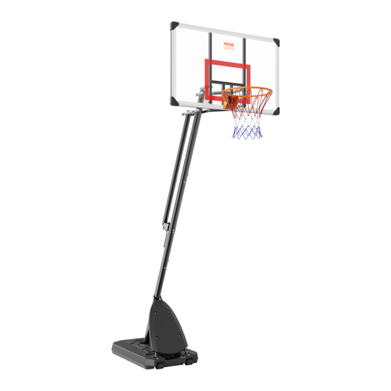
Summary of Contents for VEVOR B025B
-
Page 5: Part List
Part List Part#, Description, Picture, Quantity Bottom Pole Middle Pole Φ75*1090mm Φ75*1090mm QTY:1 QTY:1 Top Pole Bottom Pole Brace Φ75*1035mm Φ25*905mm QTY:1 QTY:2... - Page 6 Lower Handle Bar( pre-installed ) Upper Handle Bar ( pre-installed ) QTY:1 QTY:1 Short Backboard Connecting Tube Long Backboard Connecting Tube Φ32*495mm Φ32*695mm QTY:2 QTY:2 Backboard 127*78*0.2cm QTY:1 QTY:1 Base QTY:1 QTY:1 Bolt, Washerand Nut Set Backboard Connecting Plate M8*65mm QTY:2 QTY:1 Bolt, Washer Set...
- Page 7 Bolt,Washer Bolt,Washer M8*90mm M12*160mm QTY:2 QTY:2 Bolt,Washer,Nut M8*100mm Middle Pole Mounting Plate QTY:1 QTY:1 Wheel QTY:2 Wheel Axle QTY:2 Round Plate Tube Washer Φ110*2.0mm Φ13Φ19*14mm QTY:1 QTY:2 Bolt,Washer,Nut Bolt, Washer M8*85mm M8*45mm QTY:4 QTY:4 Bolt, Nut ( pre-in stalled ) Bolt,Washer,Nut M12*160mm 5*25mm...
- Page 8 Crank Handle ( pre-installed ) Cover φ10*200 + φ16*54mm QTY:1 QTY:1 Bolt, Washer and Nut Set Bolt, Washer and Nut Set M6*45mm M8*25mm QTY:4 QTY:4 Washer ( pre-installed ) Bolt, Washer and Nut Set 25*12.5*1.0mm M12*55mm QTY:2 QTY:4 Plate QTY: 1 - 7 -...
-
Page 9: Required Tools
REQUIRED TOOLS Include 10*13 Wrench Include 17*19 Wrench Include M5 Wrench Include M6 Wrench Include M8 Wrench Include M10 Wrench - 8 -... - Page 10 STEP 1 Attach Bottom Pole (#1) to Base(#12) as shown. Secure the bottom pole to the base with 2 sets of Bolts and Washers (#16) and round plate (#24) as shown. Hardware Needed Bolt, Washer Set M8*40mm QTY:2 STEP 2 Lock the Bottom Pole Braces (#4) to Base (#12) with 4 sets of Bolts, Washers, and Nuts (#34).
- Page 11 STEP 3 Attach the Bottom Pole Braces (#4) to Bottom pole (#1) with a set of Bolt, Washer and Nut (#19). Hardware Needed Bolt,Washer,Nut M8*100mm QTY:1 STEP 4 Insert Axles (#22) into the Wheels (#21) as shown. Then press down over the wheels to snap the Axles in place.
- Page 12 STEP 5 Secure Cover (#33) to Bottom Pole Braces (#4) using 6 sets of Bolts, Washers and Nuts (#35). Hardware Needed Bolt, Washer and Nut Set M6*45mm QTY:4 STEP 6 Secure Mounting Plate (#20) and Plate (#38) to Middle Pole (#2) with 2 sets of Bolts, Washers, and Nuts (#17) .
- Page 13 STEP 7 Secure Middle Pole (#2) to Bottom Pole (#1) with 2 sets of Bolts, Washers, and Nuts (#25). Hardware Needed Bolt,Washer,Nut M8*85mm QTY:2 STEP 8 Hardware Needed Bolt, Washer M8*45mm QTY:4 - 12 -...
- Page 14 STEP 9 Secure two Backboard Connecting Plates (#13) to Backboard (#9) with 4 sets of Bolts, Washers, and Nuts (#15). Hardware Needed Bolt, Washer and Nut Set M10*40mm QTY:4 STEP 10 a. Attach two Short Connecting Tubes (#7) to Upper Parts of two Backboard Connecting Plates (#13) with 2 sets of Bolts, Washers, and Nuts (#36).
- Page 15 STEP 11 Attach Short Connecting Tubes (#7) and Long Connecting Tubes (#8) to the Top Pole (#3) as shown. Secure them with 2 sets of Bolts, Washers, and Nuts (#18). Hardware Needed Bolt,Washer M12*160mm QTY:2 - 14 -...
- Page 16 STEP 12 a . Insert the Bolt (#31) through a Long Connecting Tube (#8), a Tube Washer (#23), the Upper Handle Bar (#6), the other Tube Washer (#23) and the other Long Connecting Tube (#8) in order. Then tighten the nut to lock them. b.
- Page 17 STEP 14 Please check all the bolts and nuts are all tightened after assembly. Always check the unit to ensure that the base is full of water or sand, and all fittings and hardware are tight before each use. WARNING Sand is more recommended instead of water.
- Page 18 STEP 16 Please follow the below pictures to rotate the Crank Handle (#32) to adjust height. - 17 -...
- Page 19 T e c h n i c a l S u p p o r t a n d E - Wa r r a n t y C e r t i f i c a t e w w w . v e v o r . c o m/ s u p p o r t S a n v e n T e c h n o l o g y L t d .


Need help?
Do you have a question about the B025B and is the answer not in the manual?
Questions and answers