Advertisement
Quick Links
Advertisement

Related Manuals for MOBA CB.D2.CAN


Summary of Contents for MOBA CB.D2.CAN
- Page 1 USER MANUAL CONTROL PANEL CB.D2.CAN...
- Page 2 Copyright © MOBA Mobile Automation Australia Pty Ltd MCE Lasers ® is a registered trademark of MOBA Mobile Automation Australia Pty Ltd All rights reserved. No part of this manual may be reproduced in any form or by any means without prior written permission from the publishers.
- Page 3 Repairs made out of warranty MOBA Australia or its authorised service centre will repair or replace, at its option, any defective part or component of which notice has been given during the warranty period. If service in the field is necessary to repair machine-mounted equipment under warranty, MOBA Australia may authorize on-site repairs at no charge for parts and labour.
- Page 4 6. Any external power supply must be rated between 12 and 24 Volts DC. Caution: Be sure your hands are dry before handling the machine battery terminals or power cables. © Copyright MOBA Mobile Automation Australia Pty Ltd...
- Page 5 5.1.2 Dead Band Adjustments..................32 5.1.2.1 Setting Dead Band..................33 5.1.3 Proportional Range.....................34 5.1.4 Control Range.....................34 5.1.5 Measurement Mode....................35 Grade to Zero Operations....................35 5.3 Reference/Set Target/Offset..................36 5.3.1 To Select the Reference..................36 5.3.2 To Adjust the Reference/Offset................36 © Copyright MOBA Mobile Automation Australia Pty Ltd...
- Page 6 6.1 Mast Working Screen ....................48 6.2 Mast Function Keys .....................48 6.3 Adjusting Mast Position ....................49 6.4 Relative Offset ......................50 7 Reset to System Default......................52 8 Joystick Type (Optional).......................53 9 Practical Example.........................55 10 Specifications........................57 © Copyright MOBA Mobile Automation Australia Pty Ltd...
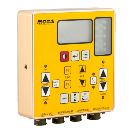
- Page 7 HYDRAULIC/AUX Figure 1.1 The CB.D2.CAN is a control panel for single machine control application. The CB.D2.CAN has a single control for valve actuation and dual control for auxiliary valves. The system provides the user with the flexibility to independently use single or multiple valve control.
- Page 8 Grade to Zero Key - set the value of the connected sensor or mast to zero (not available for all sensor types) Mast Ref - use to access the mast reference menu. Mast Key - to move the mast up and down Figure 2.2.1 © Copyright MOBA Mobile Automation Australia Pty Ltd...
- Page 9 = [REF] key = [LEFT A/M] button = [A/M] key = [RIGHT A/M] button = [AUX] key = [FUNC] key FUNC = [HYD] key = [MAST] key MAST DOWN DOWN Figure 2.3.1 © Copyright MOBA Mobile Automation Australia Pty Ltd...
- Page 10 Figure 2.5.1 Both orange arrows flashing = large downward deviation. Need to raise the bucket/blade. Bottom orange arrows flashing = very large downward deviation. Need to raise the bucket/blade by a lot. © Copyright MOBA Mobile Automation Australia Pty Ltd...
- Page 11 2.7 LOW BATTERY WARNING If the battery voltage drops below the level required to operate the unit, a low battery symbol will appear on the LCD briefly before the unit automatically shuts down. Figure 2.7.1 © Copyright MOBA Mobile Automation Australia Pty Ltd...
- Page 12 This chapter will provide you with information on getting started, connections and setting up. In addition, a description of the symbols and displays used in the working window will be explained. 3.1 BASIC SETUP The CB.D2.CAN control panel can be setup in multiple different configurations as illustrated below. CB.D2.CAN DUO²...
- Page 13 5. Connect the hydraulic valves to the connector labelled ‘HYDRAULIC/AUX’ on the CB.D2.CAN using A.RS.080 cable. The end of the cable with the bare wires should be connected to the valves as explained in the following section. Note that the hydrauli valves are normally part of the machine and are not supplied by the MOBA Australia.
- Page 14 First Step 3.4 HYDRAULIC VALVES CONFIGURATION The CB.D2.CAN can manually and automatically drive most of the commercially available solenoid valves, including popular brands such as Danfoss, Eaton-Vickers, Rexroth and others. It has four different types of hydraulic output drive signal available, suitable for different types of valves as explained in the table below.
- Page 15 * In cases where valve pins are not numbered, use the position of the straight pin relative to the other pins as shown in the pin layout to determine which pin is which. © Copyright MOBA Mobile Automation Australia Pty Ltd...
- Page 16 First Step The CB.D2.CAN can optionally drive an additional On/Off type valve which can be used for auxiliary functions such as, for example, moving a wheel up and down on a skid steer machine. This hydraulic output can normally only be activated manually using the Aux Up and Down buttons.
- Page 17 Check all system components for obvious damage, all cable connections for securely fitted connections and the sensor for secure and accurate mounting. When starting up the CB.D2.CAN ensure that no person or objects are located within range of the moving parts of the machine.
- Page 18 When finished, use [AUX] key to select ‘Exit’ and press [ENTER] key. Hydraulic Type Type [IO] Proportional [VO] General Settings Proportional [IO] Calibration On/Off (Low Side) Advance Settings On/Off (High Side) Exit Exit Figure 3.7.1.1 © Copyright MOBA Mobile Automation Australia Pty Ltd...
- Page 19 These include hydraulic oil pressure, size of the blade or bucket being moved, valve brand, sensor connected to the CB.D2.CAN and others. Because of this, there is not one set of correct settings to use. The following sections give an explanation of each of the settings to help the user optimise the overall hydraulic response.
- Page 20 6. Man speed up: Controls the movement speed of hydraulic up when using the buttons on the control panel. 7. Man speed down: Controls the movement speed of hydraulic down when using the buttons on the control panel. © Copyright MOBA Mobile Automation Australia Pty Ltd...
- Page 21 8. Man speed up: Controls the movement speed of hydraulic up when using the buttons on the control panel. 9. Man speed down: Controls the movement speed of hydraulic down when using the buttons on the control panel. © Copyright MOBA Mobile Automation Australia Pty Ltd...
- Page 22 Pulse Up and Max Pulse Dn to be equal with a value of 1/Sampling x 1000. For example, if ‘F-Sampling’ is set to 4Hz, set all to 1/4 x 1000 = 250ms. © Copyright MOBA Mobile Automation Australia Pty Ltd...
- Page 23 Use the [AUX] key to adjust the value of DOWN minimum for down. DOWN Use the [MENU] key to return back to the 100 100 calibration menu. Figure 3.7.3.1.1 © Copyright MOBA Mobile Automation Australia Pty Ltd...
- Page 24 In hydraulic’s ‘Calibration’ menu, using [AUX] key, select the option Max Test then press the [ENTER] key to begin the Max Pulse calibration. Min Test MAX PULSE Test Max Test Exit DOWN DOWN Figure 3.7.3.2.1 © Copyright MOBA Mobile Automation Australia Pty Ltd...
- Page 25 3.7.4 ADVANCED SETTINGS (HYDRAULICS) The Advanced settings for hydraulics can be used in special cases where hydraulic response remain unsatisfactory after careful adjustment of the General hydraulic settings. Currently, these settings are only available to MOBA Australia service technicians and distributors. Type [IO]...
- Page 26 0.82 When unit is in this mode, blade/bucket movement is only controlled by the user using the [HYD] UP or DOWN buttons, or by using the joystick if fitted. Figure 4.2.1 © Copyright MOBA Mobile Automation Australia Pty Ltd...
- Page 27 ZERO Figure 4.3.1 The CB.D2.CAN has the ability to control auxiliary On/Off type valves which can be used for user defined applications such as smudge bar control. These can only be operated manually using the [AUX] up/down keys and only while not inside a menu or a sub-menu.
- Page 28 3. Auto - If this option is selected the backlight will come on if a key is pressed and automatically switched off after 5 seconds of user inactivity. Use the [AUX] key to select exit and press [ENTER] key to exit menu. © Copyright MOBA Mobile Automation Australia Pty Ltd...
- Page 29 LED Brightness LED Brightness Exit Exit Figure 4.4.2.1 The setting will start to flash. Using [AUX] key, adjust the contrast to suit your eyes and cabin light conditions. Press [ENTER] key when done. © Copyright MOBA Mobile Automation Australia Pty Ltd...
- Page 30 The ‘LED Brightness’ setting will start to flash and the panel LEDs will turn ON to show the brightness. Using [AUX] key, adjust the ‘LED Brightness’ to suit your eyes and cabin light conditions. Press [ENTER] key when done. © Copyright MOBA Mobile Automation Australia Pty Ltd...
- Page 31 GNSS Sensor [Left] GNSS Sensor [Left] Response [Off] General Settings Dead Band 10mm Calibration Prop Range 127mm Parameter Settings Ctrl Range [Off] Copy to Right --mm Exit Measure Mode= [ABS] Figure 5.1 © Copyright MOBA Mobile Automation Australia Pty Ltd...
- Page 32 Laser sensor - R.ULS.CAN Laser sensor - R.ULS.MM.CAN ±1.0mm to ±30mm Slope sensor - UG.000.CAN ±0.2% to ±10% GPS sensor ±1.0mm to ±50mm Table 5.1.2.1 Note: Deadband setting is not available when response is enabled. © Copyright MOBA Mobile Automation Australia Pty Ltd...
- Page 33 Laser P Sensor Laser P Sensor Response [Off] Response [Off] Dead Band =+ 1.14% Dead Band =+ 1.14% Prop Range 4.8% Prop Range 4.8% Control Range= [Off] Control Range= [Off] Exit Exit Figure 5.1.2.1.1 © Copyright MOBA Mobile Automation Australia Pty Ltd...
- Page 34 SELECTABLE CONTROL RANGE ±3mm to 98mm Laser sensor - R.ULS.CAN Laser sensor - R.ULS.MM.CAN ±1mm to 128mm Slope sensor - UG.000.CAN 1% to 60% GPS sensor ±1mm to 128 mm Table 5.1.4.1 © Copyright MOBA Mobile Automation Australia Pty Ltd...
- Page 35 Relative. To revert back to Absolute mode, access sensor settings menu, select measure mode and press enter. ABS is then shown in the square brackets. Note: On power down, the CB.D2.CAN retains the previously used measurement mode. It is important before beginning a new job to ensure that the correct measurement mode is selected.
- Page 36 From the Ref menu screen, use the [AUX] key to highlight the reference/offet, then press the [ENTER] key. The value will start to flash. Now use the [AUX] key to adjust the reference/offset value. Press [ENTER] key when finished adjusting. © Copyright MOBA Mobile Automation Australia Pty Ltd...
- Page 37 Ref3 = +2.15 Figure 5.3.4.1 The currently selected Ref can also be adjusted from the Standard Screen without entering Ref menu. Simply press [FUNC] key’s Up or Down button to adjust the value. © Copyright MOBA Mobile Automation Australia Pty Ltd...
- Page 38 The next window will prompt you with 'Are you sure you want to do calibration?'. Simply select [YES] and hit [ENTER] key “Calibration Done” will be displayed. See figure on the next page. © Copyright MOBA Mobile Automation Australia Pty Ltd...
- Page 39 U-turn, with no other required adjustments. Available only for slope sensors. Slope [%] Slope [%] Slope [%] Slope [%] Ref = 0.50 Ref = 0.50 0.82 0.82 Figure 5.4.1.2.1 After U-turn © Copyright MOBA Mobile Automation Australia Pty Ltd...
- Page 40 Ensure that the laser transmitter is stable and the beam is within the laser sensors upper and lower limits. Refer to general sensor settings in section 5.1 for adjusting the laser sensor parameters. LASER SENSOR TYPES R.ULS.CAN and R.ULS.MM.CAN R.ULS.MM.CAN R.ULS.CAN Figure 5.4.2.1 © Copyright MOBA Mobile Automation Australia Pty Ltd...
- Page 41 R.ULS.CAN Cable A.RS.001.NC FUNC MAST (6.0m) MAST DOWN DOWN ZERO 12-24 V DC SENSOR/MAST JOYSTICK(S) HYDRAULIC/AUX 12-24v Battery Hydraulic Cable DOWN A.RS.080 (5.0m) A.RS.111 A.RS.110 Strain Sensor Optional Joystick A.RS.082 Figure 5.4.3.1 © Copyright MOBA Mobile Automation Australia Pty Ltd...
- Page 42 The Load Override Activation Threshold can alternatively be set through the menu: Hydraulic Settings Press [MENU] button. Sensor Settings Select 'Accessory Settings' and press [ENTER] Accessory Sensors button. Joystick LCD/LED Settings Advanced Settings Exit Figure 5.4.3.1.1 © Copyright MOBA Mobile Automation Australia Pty Ltd...
- Page 43 Voltage Proportional [VO] type, the following Max Down 25.0% menu will appear. Direction Normal Exit Figure 5.4.3.1.2 All these settings have the same meaning as for normal operation and should be set according to the same instructions. © Copyright MOBA Mobile Automation Australia Pty Ltd...
- Page 44 The fifth setting, 'Set Zero' is normally a factory set setting for initial calibration of the HP Load Sensor with zero load. The user should not normally have to use this setting. © Copyright MOBA Mobile Automation Australia Pty Ltd...
- Page 45 To set this threshold: Hydraulic Settings Sensor Settings Press [MENU] button. Accessory Sensors Select 'Accessory Settings' and press [ENTER] Joystick LCD/LED Settings button. Advanced Settings Select 'Sensor Settings' and press [ENTER] Exit button. Figure 5.4.3.1.4 © Copyright MOBA Mobile Automation Australia Pty Ltd...
- Page 46 - Short press both switches to copy current height position to offset - Long press both switches to reset height and offset to zero - Zero GNSS height and offset ZERO - Edit and select height reference memory settings © Copyright MOBA Mobile Automation Australia Pty Ltd...
- Page 47 For Single Slope and Dual Slope go to the job target settings and dial using the [AUX] key to configure the required slope settings. Job Type [Slope] GPS Single Slope Job Target Settings Slope = +0.000% Exit Exit Figure 5.4.4.3.1 © Copyright MOBA Mobile Automation Australia Pty Ltd...
- Page 48 MAST - Open the reference screen. - Set current mast position to zero. ZERO - Press to invoke the mast reference settings. - Move the mast up or down manually. MAST DOWN © Copyright MOBA Mobile Automation Australia Pty Ltd...
- Page 49 Use [AUX] key to select and set a new reference point, then press [ENTER] key to confirm the new reference point setting. Flashing R1=+0008 RO1=+0008 R2=+0000 RO2=+0000 Flashing Flashing R1=+0008 RO1=+0020 R2=+0000 RO2=+0000 Flashing RO1=+0020 RO1=+0020 RO2=+0000 RO2=+0000 Figure 6.3.1 © Copyright MOBA Mobile Automation Australia Pty Ltd...
- Page 50 RO1 offset multiplied by the number of times the [AUX] up or down arrow key was pressed. A maximum of 7 presses can be made. Adjusting the mast height by RO2 offset is the same procedure as with adjusting the mast height by RO1 offset. © Copyright MOBA Mobile Automation Australia Pty Ltd...
- Page 51 Adjusting the mast height by RO2 offset is the same procedure as with adjusting the mast height by RO1 offset. The only difference is the joystick has to be tilted towards ‘UP’ or ‘RIGHT’ position. © Copyright MOBA Mobile Automation Australia Pty Ltd...
- Page 52 Select ‘YES’ if you want to proceed with system default. Press the [ENTER] key to execute. Are you sure to restore Default ? Factory default restored [YES] [NO] Figure 7.1 Screen will return to the main menu screen after displaying ‘Factory default restored’ screen for five seconds. © Copyright MOBA Mobile Automation Australia Pty Ltd...
- Page 53 Joystick Type 8 JOYSTICK TYPE (Optional) CB.D2.CAN supports multiple types of joysticks, so it is very important to select the right type of joystick connected to the system. From the main menu screen, use [AUX] key to select ‘Joystick’ submenu then press [ENTER] key.
- Page 54 A.RS.118 OFFSET1 (R01) SPDT (mom)-OFF-(mom) OFFSET2 (R02) SPDT (mom)-OFF-(mom) AUTO/MAN AUTO (TOGGLES) SPST (mom)-OFF HYD UP/DN SPDT (mom)-OFF-(mom) Figure 8.4 Note: Only cable with bare wires is provided. The switches are optional. © Copyright MOBA Mobile Automation Australia Pty Ltd...
- Page 55 SENSOR(S) JOYSTICK(S) JOYSTICK(S) HYDRAULIC/AUX HYDRAULIC/AUX ME.14.CAN A.RS.080 A.RS.001.NC DOWN 12-24v Battery A.RS.082 (Optional) A.ME.01 A.RS.107 (CAN Cable Option) Laser beam Scanning Laser beam hitting Dead Band Green LEDs are flashing Figure 9.1 © Copyright MOBA Mobile Automation Australia Pty Ltd...
- Page 56 3. Adjust the laser receiver by adjusting the electric mast so that the laser beam hits dead band (ie: the green LEDs are flashing). 4. On the CB.D2.CAN panel, press [ZERO] key to set the current mast height reading to zero.
- Page 57 Waterproof/Dustproof Ÿ 128*64 dots Ÿ maximum number of characters is 21 Ÿ maximum number of lines is 7 Ÿ white colour LED backlight * Specifications subject to change without notice. Table 10.1 © Copyright MOBA Mobile Automation Australia Pty Ltd...
- Page 58 Notes © Copyright MOBA Mobile Automation Australia Pty Ltd...
- Page 59 Notes © Copyright MOBA Mobile Automation Australia Pty Ltd...
Need help?
Do you have a question about the CB.D2.CAN and is the answer not in the manual?
Questions and answers