Table of Contents
Advertisement
Quick Links
Advertisement
Table of Contents

Related Manuals for MOBA DUO2.CAN


Summary of Contents for MOBA DUO2.CAN
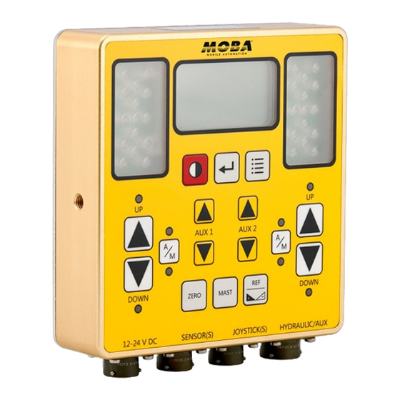
- Page 1 USER MANUAL CONTROL PANEL DUO2.CAN...
- Page 2 Copyright © MOBA Mobile Automation Australia Pty Ltd MCE Lasers ® is a registered trademark of MOBA Mobile Automation Australia Pty Ltd All rights reserved. No part of this manual may be reproduced in any form or by any means without prior written permission from the publishers.
- Page 3 Repairs made out of warranty MOBA Australia or its authorised service centre will repair or replace, at its option, any defective part or component of which notice has been given during the warranty period. If service in the field is necessary to repair machine-mounted equipment under warranty, MOBA Australia may authorize on-site repairs at no charge for parts and labour.
- Page 4 It is best to remove any electronic gear near a welding job. Any external power supply must be rated between 12 and 24 Volts DC. Caution: Be sure your hands are dry before handling the machine battery terminals or power cables. © Copyright MOBA Mobile Automation Australia Pty Ltd...
-
Page 5: Table Of Contents
5 Working with Sensors......................32 5.1 General Sensor Settings....................33 5.1.1 Response Adjustment..................33 5.1.2 Dead Band Adjustments..................34 5.1.3 Proportional Range Adjustment................35 5.1.4 Control Range Adjustment................35 5.1.5 Measurement Mode..................36 5.1.6 Offset .......................36 5.1.7 Units .........................36 © Copyright MOBA Mobile Automation Australia Pty Ltd... - Page 6 6.3 Adjusting Mast Position Using References..............49 6.3.1 Mast Search Function..................50 Adjusting Mast Position Using Relative Offset s.............51 et to System Default......................52 8 Joystick Type (optional)......................53 actical Example......................59 10 Specifications........................61 © Copyright MOBA Mobile Automation Australia Pty Ltd...
-
Page 7: Product Overview
The hydraulics valves can be actuated either automatically or manually, from the panel using keys or a joystick. The DUO2 can drive ON/OFF hydraulic valves along with PV and PI without need of any external accessory. © Copyright MOBA Mobile Automation Australia Pty Ltd... -
Page 8: User Interface
- Reverse the Polarity of the target slope when a slope sensor is connected. Zero Key - sets the value of the connected mast or sensors to zero (not available for all sensor types). Figure 2.2.1 © Copyright MOBA Mobile Automation Australia Pty Ltd... -
Page 9: Key Legend
= [REF] key = [A/M] key = [L/R] button = [AUX1] key AUX 1 = [LEFT A/M] button = [AUX2] key AUX 2 = [RIGHT A/M] button = [UP/DOWN] key Figure 2.3.1 DOWN © Copyright MOBA Mobile Automation Australia Pty Ltd... -
Page 10: Led Indication
No communication: If both top red and bottom orange arrows flash together it indicates that the panel has lost communication with the sensor. Please check the cable connection at this point. © Copyright MOBA Mobile Automation Australia Pty Ltd... -
Page 11: Configuration Menu
2.7 LOW BATTERY WARNING If the battery voltage drops below the level required to operate the unit, a low battery symbol will appear on the LCD briefly before the unit automatically shuts down. Figure 2.7.1 © Copyright MOBA Mobile Automation Australia Pty Ltd... -
Page 12: Basic Setup
Model: UG.000.CAN Serial No: 01286372 1 x LS-3000 1 x LS-3000 1 x Sonic Ski 2 x LS-3000 1 x Sonic Ski 1 x Slope Sensor 1 x Slope Sensor Figure 3.1.1 © Copyright MOBA Mobile Automation Australia Pty Ltd... -
Page 13: First Steps
1) Mount the DUO2 panel somewhere easily accessible by the operator and secure it properly. 2) Mount the IB.DUO2 or IB.DUO2.CAN or IB.DUO2.MOB (Junction Box) and connect it to the connector labelled SENSOR(S) on the DUO2 using appropriate cable listed in Table1. -
Page 14: Hydraulic Alves Onfiguration
First Steps 3.4 HYDRAULIC VALVES CONFIGURATION The DUO2.CAN can manually and automatically drive most of the commercially available solenoid valves, including popular brands such as Danfoss, Eaton-Vickers, Rexroth and others. It has four different types of hydraulic output drive signal available, suitable for different types of valves as explained in the table below. - Page 15 First Steps The DUO2.CAN is normally supplied with hydraulic cable A.RS.080 which has colour- coded and labelled bare wires on one end allowing the user to connect their valve according to the particular hydraulic output type requirement for that valve.
-
Page 16: Powering P U
First Steps The DUO2.CAN can optionally drive an additional On/Off type valve which can be used for auxiliary functions such as, for example, moving a wheel up and down on a skid steer machine. This hydraulic output can normally only be activated manually using the Aux Up and Down keys. -
Page 17: Working Creen S
Using [AUX2] key select the side and then press [ENTER] key. Left Side Left Side Right Side Hydraulic Settings Accessory Sensors Sensor Settings LCD/LED Settings Disable Sensor Advanced Settings Exit Exit Figure 3.7.2 © Copyright MOBA Mobile Automation Australia Pty Ltd... -
Page 18: Selecting Ype Of Ydraulics
Hydraulic - Left Hydraulic - Left Proportional (VO) Type [IO] General Settings Proportional (IO) On/Off (Low Side) Calibration On/Off (High Side) Advance Settings MOBA Gateway Copy to Right Exit Exit Figure 3.7.1.3 © Copyright MOBA Mobile Automation Australia Pty Ltd... -
Page 19: Adjusting The S Ettings For Ydraulic H Response
DUO2 and others. Because of this, there is not one set of correct settings to use. The following sections give an explanation of each of the settings to help the user optimise the overall hydraulic response. © Copyright MOBA Mobile Automation Australia Pty Ltd... -
Page 20: General Settings - Vo Hydraulics
(Maximum is 100%). 7. Man Speed Dn: In manual mode, this is the setting for rate of speed of the hydraulics in downward direction when down arrow, [UP/DOWN] key, is pressed (Maximum is 100%). © Copyright MOBA Mobile Automation Australia Pty Ltd... -
Page 21: General Settings - Io Hydraulics
7. Direction: Normal or Reverse direction for hydraulics movement. When Reverse direction is selected, the DUO2 will activate Down hydraulics when up control is applied and will activate UP hydraulics when down signal is applied. © Copyright MOBA Mobile Automation Australia Pty Ltd... -
Page 22: General Settings - On/Off Hydraulics
Down, Max Pulse Up and Max Pulse Down to be equal with a value of 1/Sampling x 1000. For example, if ‘F-Sampling’ is set to 4Hz, set all to 1/4 x 1000 = 250ms. © Copyright MOBA Mobile Automation Australia Pty Ltd... -
Page 23: Calibration - Ydraulics H
Note: During the test, the hydraulic cylinder may end up moving to the limit in one direction. Manually move the cylinder back in the middle of its working range before continuing with the test. © Copyright MOBA Mobile Automation Australia Pty Ltd... -
Page 24: Max Pulse Calibration (Hydraulics)
This can be done by adjusting the Min and Max settings through the menu without entering ‘Calibration’ mode. Note2: Section 3.7.3.1 and section 3.7.3.2 are descriptions of the calibration procedure for the left side. A similar procedure should be followed for the right side. © Copyright MOBA Mobile Automation Australia Pty Ltd... -
Page 25: Advanced Ettings ( Ydraulics) S H
The ‘Advanced Settings’ for hydraulics can be used in special cases where hydraulic response remains unsatisfactory after careful adjustment of the General hydraulic settings. Currently, these settings are only available to MOBA Australia service technicians and distributors. Hydraulic - Left... -
Page 26: Working With Anel P
Similarly the right side down key can be used to manually activate the valves to move the right side of the blade down. DOWN © Copyright MOBA Mobile Automation Australia Pty Ltd... -
Page 27: Setting The Alve Ontrol Ode
The user should be on guard to immediately switch to Manual hydraulic control or switch the unit off. © Copyright MOBA Mobile Automation Australia Pty Ltd... -
Page 28: Setting The Auxiliary Keys Function
1 and auxiliary 2 hydraulics up or down. With Aux Keys = Reference, the Keys increase or decrease the connected sensor Ref values. Note: If in mast screen, The Aux Keys move the mast up or down. © Copyright MOBA Mobile Automation Australia Pty Ltd... -
Page 29: Auxiliary Control
Hydraulic = Unlocked Hydraulic = Unlocked Auto/Man = Unlocked Auto/Man = Unlocked MAST = Unlocked MAST = Unlocked <-x-> Hydraulic <---> Hydraulic Auxiliary 2 = Off Auxiliary 2 = On Figure 4.4.3 © Copyright MOBA Mobile Automation Australia Pty Ltd... -
Page 30: Lcd/Led Settings
Working with Panel 4.5 LCD/LED SETTINGS From the main menu screen, use [AUX2] key to scroll down to ‘LCD/LED Settings’ and then press [ENTER] key to access the sub menu. Left Side LCD Backlight Right Side LCD Contrast Accessory Sensors Reverse LCD LCD/LED Settings LED Brightness... -
Page 31: Lcd Contrast
The ‘LED Brightness’ setting will start to flash. And the panel LEDs will turn on to show the brightness. Using [AUX2] key adjust the ‘LED Brightness’ to suit your eyes and cabin light conditions. Press [ENTER] key when done. © Copyright MOBA Mobile Automation Australia Pty Ltd © Copyright MOBA Mobile Automation Australia Pty Ltd... -
Page 32: Working With Sensors
GNSS Sensor [Left] GNSS Sensor [Left] Response [Off] General Settings Dead Band 10mm Calibration Prop Range 127mm Parameter Settings Ctrl Range [Off] Copy to Right --mm Exit Measure Mode= [ABS] Figure 5.1 © Copyright MOBA Mobile Automation Australia Pty Ltd... -
Page 33: General Sensor Settings
Slope Sensor [Left] Slope Sensor [Left] Response Response Dead Band 0.50% Dead Band 0.50% Prop Range 20.0% Prop Range 20.0% Ctrl Range [On] Ctrl Range [On] 30.0% 30.0% Exit Exit Figure 5.1.1.1 © Copyright MOBA Mobile Automation Australia Pty Ltd... -
Page 34: Dead Band Adjustments
Laser Sensor [Left] Laser Sensor [Left] Response [Off] General Settings Dead Band 10mm Calibration Prop Range 127mm Parameter Settings Ctrl Range [Off] Copy to Right --mm Exit Measure Mode= [ABS] Figure 5.1.2.1 © Copyright MOBA Mobile Automation Australia Pty Ltd... -
Page 35: Proportional Range Adjustment
1 mm to 128 mm Slope sensor - UG.000.CAN ± 1% to 60% Sonic sensor - SKIS-1500 ± 1.0 mm to 1500 mm ± GPS sensor 1.0 mm to 128 mm Table 5.1.4.1 © Copyright MOBA Mobile Automation Australia Pty Ltd... -
Page 36: Measurement Mode
Select between various units of measurement for different sensor. Different units available for different sensors are: Slope Sensor : Percentage [%] Degree [ ° ] Laser Sensor : Centimetre [cm] Millimetre [mm ] © Copyright MOBA Mobile Automation Australia Pty Ltd... -
Page 37: Sensor References
Use the [AUX] keys to select the side/sensor to access, then LEFT LEFT AUX 2 press [ENTER] key to bring RIGHT RIGHT up the reference menu for that side/sensor. Ref1=+0.00 LEFT Ref2=+0.00 RIGHT Figure 5.2.2 © Copyright MOBA Mobile Automation Australia Pty Ltd... -
Page 38: Adjusting Stored Sensor References
From the Reference menu screen, use [AUX] keys to highlight one of the Ref1 - Ref4, then press and hold the [ENTER] key until the current sensor value is transferred to the selected Ref. Press and Hold Ref3=+2.15 Ref3=-1.52 Ref4=+2.50 Ref4=+2.50 Figure 5.2.31 © Copyright MOBA Mobile Automation Australia Pty Ltd... -
Page 39: Grade To Zero Operation
The current sensor value for that side will become zero. Note: 1. Some sensor models do not support grade zero. 2. Grade to zero for laser sensors only works if beam is hitting the sensor. © Copyright MOBA Mobile Automation Australia Pty Ltd... -
Page 40: Sensor Types
It gets pushed to the left side only if another sensor is plugged on the right. © Copyright MOBA Mobile Automation Australia Pty Ltd... -
Page 41: Calibrating The Slope Sensor
Side Mini Stick Aux Keys = Reference Aux Keys = Reference Ref Edit = Unlocked Ref Edit = Unlocked Hydraulic = Unlocked Hydraulic = Unlocked Auto/Man = Unlocked Auto/Man = Unlocked Figure 5.4.1.3.1 © Copyright MOBA Mobile Automation Australia Pty Ltd... -
Page 42: Inverting The Grading Target For Slope Sensor
U-turn, with no other required adjustments. Available only for slope sensors. Laser [mm] Slope Laser [mm] Slope Ref= Ref4= 2.50 Ref= Ref4= -2.50 -076 -1.52 -076 +1.52 After U-turn AUTO AUTO Figure 5.4.1.4.1 © Copyright MOBA Mobile Automation Australia Pty Ltd... -
Page 43: Sonic Ski
Sonic Ski bracket (MOB.236). For parameter settings, refer to general sensor settings in section 5.1. L BRACKET MOB.236 A.ME.15 MOB.007 Sonic Ski Plus 330 - 370mm BLADE CURB Figure 5.4.2.1 © Copyright MOBA Mobile Automation Australia Pty Ltd... -
Page 44: Laser Sensor
Ensure that the laser transmitter is stable and the beam is within the laser sensors upper and lower limits. Refer to general sensor settings in section 5.1 for adjusting the laser sensor parameters. LASER SENSOR TYPES R.ULS.CAN and R.ULS.MM.CAN - Setup using IB.DUO2.CAN. LS-3000 - Setup using IB.DUO2.MOBA. R.ULS.MM.CAN LS-3000 ME.14... -
Page 45: Gnss Sensor
- Zero left side GNSS height and offset ZERO - Edit and select height reference memory settings (Long press required in case slope sensor is active on right side of DOU2 to access memory reference settings) © Copyright MOBA Mobile Automation Australia Pty Ltd... -
Page 46: Gnss Job Type Selection And Setup
For Single Slope and Dual Slope go to the job target settings and use [AUX2] key to configure the required slope settings. Job Type [Slope] GPS Single Slope Job Target Settings Slope 1 = +0.000% Exit Exit Figure 5.4.4.3.5 © Copyright MOBA Mobile Automation Australia Pty Ltd... -
Page 47: Gnss Auto Mode
(Ref at the top of the screen) automatically set to GNSS cross slope (S2 at the bottom left of the screen). GPS üü 0008 Rgps 1.23 Ref = 1.23 S1 -4.321% -0011 -13.7 1.234% 1.234% AUTO Figure 5.4.4.4.3 © Copyright MOBA Mobile Automation Australia Pty Ltd... -
Page 48: Mast Mode Of Operation
- Invokes a particular highlighted Reference value while in the Reference Menu. - Move the mast up and down, Aux 1 Keys for left connected AUX 1 AUX 2 mast, Aux 2 Keys for right connected mast. © Copyright MOBA Mobile Automation Australia Pty Ltd... -
Page 49: Adjusting Mast Position Using References
To invoke one of the R1 - R4, after exiting edit mode, use the Aux Keys to highlight one of R1 - R4 and then press [MENU] Key. The screen will revert to the standard mast screen and the mast will move to the selected position. © Copyright MOBA Mobile Automation Australia Pty Ltd... -
Page 50: Mast Search Function
Zero MAST’ message appears on power MAST up. Zero the mast position first. 2) Search function will not work without a laser sensor connected. The laser sensor Figure 6.3.1.3 must be mounted to the mast. © Copyright MOBA Mobile Automation Australia Pty Ltd... -
Page 51: Adjusting Mast Position Using Relative Offsets
Note: If RO1 or RO2 are set to a value of zero (default), mast position will not change. To adjust the mast height by RO1 or RO2 using optionally supplied joystick, refer to section 8 explanation, for ‘Prop Mini Stick/Mast’ or ‘Mast Offset Stick’. © Copyright MOBA Mobile Automation Australia Pty Ltd... -
Page 52: Reset To System Default
Screen will return to the ‘Advanced Settings’ menu after displaying ‘Factory Defaults Restored’ for five seconds. Set Default Slope Side = [None] Aux Keys = Reference Ref Edit = Unlocked Hydraulic = Unlocked Auto/Man = Unlocked MAST = Unlocked © Copyright MOBA Mobile Automation Australia Pty Ltd... -
Page 53: Joystick Type (Optional)
DOWN LEFT DOWN LEFT UP RIGHT UPLEFT DOWN RIGHT NOT VALID NOT VALID UP RIGHT UP LEFT BOTH DOWN BOTH UP NOT VALID NOT VALID BOTH UP Note the gland position Figure 8.2 © Copyright MOBA Mobile Automation Australia Pty Ltd... - Page 54 Notes: 1) On power up, mode always defaults to Standard Mode. 2) Selecting this joystick type automatically sets menu option Auxiliary 2 = OFF/ON to ON to enable control of Auxiliary 2. © Copyright MOBA Mobile Automation Australia Pty Ltd...
- Page 55 (f) Proportional Toggle Stick - works in the same manner as ‘Proportional Mini Stick’, however power supply and signal out levels differ to accommodate DANFOSS type proportional joysticks (not limited to this brand). © Copyright MOBA Mobile Automation Australia Pty Ltd...
- Page 56 Activates left hydraulics up or HYD UP/DN SPDT down. (mom)-OFF-(mom) Figure 8.8 Note: Only cable A.RS.118 with unterminated wires is supplied. The switches can be supplied optionally or sourced by the user. © Copyright MOBA Mobile Automation Australia Pty Ltd...
- Page 57 Adjusting the mast height by RO2 offset is the same procedure as with adjusting the mast height by RO1 offset, the only difference is the joystick has to be tilted towards ‘UP RIGHT’ or ‘DOWN RIGHT’ position. © Copyright MOBA Mobile Automation Australia Pty Ltd...
- Page 58 Where skid steer joystick buttons are not enough for an Auto/Manual function, the following quick sequence can be used to switch between Auto and Manual: 1) Press DOWN LEFT button once. 2) Double click UP LEFT button. © Copyright MOBA Mobile Automation Australia Pty Ltd...
-
Page 59: Practical Example
A.RS.080 DOWN LEFT SIDE RIGHT SHIFT A.RS.111 LEFT BLADE ROTATION RIGHT CONTROL BOX A.RS.106 A.RS.106 IB.DUO2.CAN ME.15 ME.15 Laser beam Scanning Laser beam hitting Dead Band Green LEDs are flashing Figure 9.1 © Copyright MOBA Mobile Automation Australia Pty Ltd... - Page 60 MAST Laser [mm] Laser [mm] Laser [mm] Laser [mm] Ref= Ref= Ref= Ref= 0.52 1.02 1.02 Laser [mm] Laser [mm] Laser [mm] Laser [mm] Ref= Ref= Ref= Ref= AUTO AUTO Figure 9.2 © Copyright MOBA Mobile Automation Australia Pty Ltd...
-
Page 61: Specifications
Waterproof/Dustproof Ÿ 128*64 dots Ÿ maximum number of characters is 21 Ÿ maximum number of lines is 7 Ÿ white colour LED backlight * Specifications subject to change without notice. Table 10.1 © Copyright MOBA Mobile Automation Australia Pty Ltd... - Page 62 Notes © Copyright MOBA Mobile Automation Australia Pty Ltd...
- Page 63 Notes © Copyright MOBA Mobile Automation Australia Pty Ltd...
Need help?
Do you have a question about the DUO2.CAN and is the answer not in the manual?
Questions and answers