Advertisement
Quick Links
Multi-zone Installation Manual Table of Contents:
Outdoor unit installation page 2
Standard wall mount installation page 47
Ceiling Cassette installation page 89
Low wall air handler installation 107
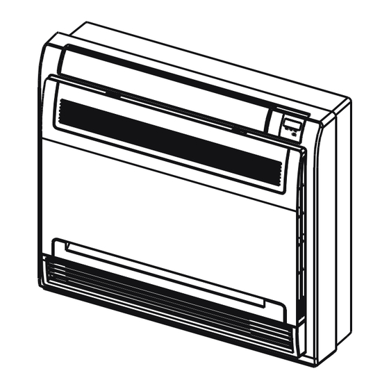
Wall/Ceiling (also referred to as floor/ceiling) installation page 134
Concealed duct air handler installation page 150
Advertisement

Related Manuals for Blueridge M4 Series


Summary of Contents for Blueridge M4 Series
- Page 1 Multi-zone Installation Manual Table of Contents: Outdoor unit installation page 2 Standard wall mount installation page 47 Ceiling Cassette installation page 89 Low wall air handler installation 107 Wall/Ceiling (also referred to as floor/ceiling) installation page 134 Concealed duct air handler installation page 150...
- Page 2 INVERTER ONE-TWO/ONE-THREE/ONE-FOUR/ONE-FIVE SPLIT-TYPE AIR CONDITIONER Owner’s Manual & Installation Manual IMPORTANT NOTE: Read this manual carefully before installing or operating your new air conditioning unit. Make sure to save this manual for future reference. Please check the applicable models, technical data, F-GAS(if any) and manufacturer information from the “Owner's Manual - Product Fiche ”...
- Page 3 Table of Contents ................ Safety Precautions Owner’s Manual ........... Unit Parts And Major Functions 1. Unit Parts .....................................08 2. Operating temperature ..............................10 3. Features ....................................11 .......... Manual Operations And Maintenance ................Troubleshooting...
- Page 4 Installation Manual ..................Accessories ................. Installation Summary ................Installation Diagram ..................Specifications ..............Outdoor Unit Installation 1. Select installation location ..............................21 2. Install drain joint ..................................22 3. Anchor outdoor unit ................................22 ............Refrigerant Piping Connection 1. Cut pipe ......................................24 ...................................24 2.
- Page 5 Safety Precautions Read Safety Precautions Before Operation and Installation Incorrect installation due to ignoring instructions can cause serious damage or injury. The seriousness of potential damage or injuries is classified as either a WARNING or CAUTION. CAUTION WARNING This symbol indicates the possibility of This symbol indicates the possibility property damage or serious consequences.
- Page 6 CLEANING AND MAINTENANCE WARNINGS Do not clean the air conditioner with combustible cleaning agents. Combustible cleaning agents • can cause re or deformation. CAUTION Turn o the air conditioner and disconnect the power if you are not going to use it for a long time. •...
- Page 7 WARNINGS FOR PRODUCT INSTALLATION 2. Installation must be performed according to the installation instructions. Improper installation can cause water leakage, electrical shock, or re. (In North America,installation must be performed in accordance with the requirement of NEC and CEC by authorized personnel only.) 3.
- Page 8 Amount of refrigerant Installation height Minimum room Amount of refrigerant Installation height Minimum room to be charged (kg) area (m²) to be charged (kg) area (m²) 0.6 /1.8 /2.2 9 /1 /1 1.95 0.6 /1.8 /2.2 33 /4 /2.5 1.05 0.6 /1.8 /2.2 9.5 /1.5 /1 0.6 /1.8 /2.2...
- Page 9 Unit Parts And Major Functions Unit Parts Wall-mounted type Duct / Ceiling type Indoor unit 1. Panel frame 2. Rear air intake grille 3. Front panel 4. Air purifying lter & Air lter(behind) Indoor unit 1. Air outlet 5. Horizontal louver 2.
- Page 10 Floor and standing type(console) Compact four-way cassette type Indoor unit Indoor unit 1. Air ow louver (at air outlet) 1. Drain pump(drain water from indoor unit) 2. Air inlet (containing air lter) 2. Drain hose 3. Remote controller 3. Air outlet 4.
- Page 11 NOTE: For multi-split type air conditioners, one outdoor unit can be matched to di erent types of indoor units. All of the pictures in this manual are for demonstration purposes only. Your air conditioner may be slightly di erent, if similar in shape. The following pages introduce several kinds of indoor units that can be matched with the outdoor units.
- Page 12 Features Protection of the air conditioner White mist emerging from the indoor unit Compressor protection • A white mist may be generated due to a large • The compressor cannot restart for 3 minutes temperature di erence between air inlet and after it stops.
- Page 13 The air conditioner turns to FAN ONLY Heating mode (For cooling and heating mode from COOL or HEAT (for cooling models only) and heating models only) mode. The air conditioner draws in heat from the When the indoor temperature reaches the set outdoor unit and releases it via the indoor unit temperature setting, the compressor will stop during heating.
- Page 14 Manual Operations And Maintenance Operation mode selection Optimal operation While two or more indoor units are To achieve optimal performance, please note the simultaneously operating, make sure the modes following: do not con ict with each other. The heat mode •...
- Page 15 Troubleshooting SAFETY PRECAUTIONS If any of the following conditions occurs, turn o your unit immediately! The power cord is damaged or abnormally warm • You smell a burning odor • The unit emits loud or abnormal sounds • A power fuse blows or the circuit breaker frequently trips •...
- Page 16 Problem Possible Causes A squeaking sound is heard when the system is OFF or in COOL mode. The The indoor unit noise is also heard when the drain pump (optional) is in operation. makes noises A squeaking sound may occur after running the unit in HEAT mode due to expansion and contraction of the unit’...
- Page 17 Troubleshooting Tips When troubles occur, please check the following points before contacting a repair company. Problem Possible Causes Solution Power failure Wait for the power to be restored The power switch is o Turn on the power The unit The fuse is burned out Replace the fuse is not Remote control batteries are dead...
- Page 18 Accessories The air conditioning system comes with the following accessories. Use all of the installation parts and accessories to install the air conditioner. Improper installation may result in water leakage, electrical shock and re, or cause the equipment to fail. The items are not included with the air conditioner must be purchased separately.
- Page 19 Installation Summary INSTALLATION ORDER (L1) (L2) Install the outdoor unit Connect the refrigerant pipes Connect the wires Evacuate the refrigeration Perform a test run system ...
- Page 20 Installation Diagram Installation Diagram Mounting screw ST3.9×25-C-H Air-break Installation plate Switch Clip anchor Air-break Switch Remote controller Drainage holder Pipe 5 4 3 Outdoor Unit Power Cable The maximum amount of the connection cables is 5. This section is for reference only.
- Page 21 Specifications Number of units that can be used Connected units 1-5 units together Compressor stop/start frequency Stop time 3 min or more voltage uctuation within ±10% of rated voltage Power source voltage voltage drop during start within ±15% of rated voltage interval unbalance within ±3% of rated voltage Unit: m/ft.
- Page 22 Outdoor Unit Installation Install the unit by following local codes and install unit in the following locations: DO NOT regulations , there may be di er slightly Near an obstacle that will block air inlets between di erent regions. and outlets Near a public street, crowded areas, or where noise from the unit will disturb others Near animals or plants that will be harmed...
- Page 23 Step 2: Install drain joint Step 3: Anchor outdoor unit (Heat pump unit only) The outdoor unit can be anchored to the ground or to a wall-mounted bracket with Before bolting the outdoor unit in place, you must bolt(M10). Prepare the installation base of the install the drain joint at the bottom of the unit.
- Page 24 (unit: mm/inch) Notes On Drilling Hole In Wall You must drill a hole in the wall for the Outdoor Unit Dimensions Mounting Dimensions refrigerant piping, and the signal cable that will W x H x D Distance A Distance B connect the indoor and outdoor units.
- Page 25 Refrigerant Piping Connection NOTE: For quick-connect models, please DO NOT DEFORM PIPE refer to the internal machine manual for the WHILE CUTTING installation method of the connecting pipe. Be extra careful not to damage, dent, or deform The external machine manual does not the pipe while cutting.
- Page 26 4. Remove PVC tape from ends of pipe when ready to perform flaring work. 5. Clamp flare form on the end of the pipe. The end of the pipe must extend beyond the flare Indoor unit tubing Pipe form. Flare nut Flare form 3.
- Page 27 7. Thread this pipeline through the wall and NOTE ON MINIMUM BEND RADIUS connect it to the outdoor unit. Carefully bend the tubing in the middle 8. Insulate all the piping, including the valves according to the diagram below. DO NOT of the outdoor unit.
- Page 28 Wiring Make sure that you do not cross your BEFORE PERFORMING ANY electrical wiring with your signal wiring. ELECTRICAL WORK, READ This may cause distortion and THESE REGULATIONS interference. 1. All wiring must comply with local and national The unit must be connected to the electrical codes, regulations and must be main outlet.
- Page 29 1. Prepare the cable for connection Air switch a. You must rst choose the right cable (purchased seperately) Indoor unit power wires size. Be sure to use H07RN-F cables. NOTE: In North America, choose the cable type according to the local electrical codes and regulations.
- Page 30 Remove the electric cover of the outdoor unit. If there is no cover on the outdoor unit, take o the bolts from the maintenance board and remove the protection board. Cover Screw 3. Connect the u-lugs to the terminals Match the wire colors/labels with the labels on the terminal block, and rmly screw the u-lug of each wire to its corresponding terminal.
- Page 31 NOTE: For quick-connector models, please refer to <<Owner’s Manual & Installation Manual >> packed with the indoor unit. NOTE: Refer to the following gures if end-users wish to perform their own wiring. Run the main power cord through the lower line-outlet of the cord clamp. ---- This symbol indicates eld wiring.
- Page 32 S(A) L(A) N(A) L(B) N(B) S(B) L(A) N(A) S(A) L(B) N(B) S(B) L(1) L(1) TO A TO A SUPPLY SUPPLY Model M Model N Model O Model P Model Q Model R 1(A) 2(A) 3(A) 1(B) 2(B) 3(B) L1 L2 L1(A) L2(A) S(A)
- Page 33 One-three models: Model A Model C Model B Model D Model E Model F L(A) N(A) S(A) L(B) N(B) S(B) L(C) N(C) S(C) TO A TO C TO B SUPPLY Model G Model H Model I L(C) N(C) S(C) 1(L) 2(N) 3(S) 1(L) 2(N) 3(S) 1(L) 2(N) 3(S) To indoor...
- Page 34 One-four models: Model A Model B 1(L) 2(N) 3(S) 1(L) 2(N) 3(S) 1(L) 2(N) 3(S) 1(L) 2(N) 3(S) Model D Model C L(A) N(A) S(A) L(B) N(B) S(B) L(C) N(C) S(C) L(D) N(D) S(D) TO A TO B TO A TO B SUPPLY Model E...
- Page 35 L1(C) L2(C) S(C) L1(D)L2(D)S(D) 1(C) 2(C) 3(C) 1(D) 2(D) 3(D) L1(A) L2(A) S(A) L1(B) L2(B) S(B) 1(A) 2(A) 3(A) 1(B) 2(B) 3(B) TO B TO B TO A TO C TO D TO A TO C TO D Model J Model I Model L Mode K...
- Page 36 One-five models: 1(L) 2(N) 3(S) 1(L) 2(N) 3(S) 1(L) 2(N) 3(S) 1(L) 2(N) 3(S) 1(L) 2(N) 3(S) Model B Model A Model C Model D 1(C) 2(C) 3(C) 1(D) 2(D) 3(D) 1(E) 2(E) 3(E) 1(A) 2(A) 3(A) 1(B) 2(B) 3(B) L(C) N(C) S(C) L(D) N(D) S(D) L(E) N(E) S(E) L(A) N(A) S(A) L(B) N(B) S(B) TO C...
- Page 37 L1(A) L2(A)S(A) L1(B)L 2(B) S(B) L1(C) L2(C) S(C) L1(D)L2(D) S(D) L1(E) L2(E) S(E) 1(C) 2(C) 3(C) 1(D) 2(D) 3(D) 1(E) 2(E) 3(E) 1(A) 2(A) 3(A) 1(B) 2(B) 3(B) TO A TO B TO C TO D TO E TO A TO B TO C TO D TO E...
- Page 38 Air Evacuation Preparations and Precautions 5. Pressure test Connect nitrogen tank Air and foreign matter in the refrigerant regulator to charging hose on circuit can cause abnormal rises in pressure, manifold gauges. Pressurize lineset to which can damage the air conditioner, 200 psi of dry nitrogen.
- Page 39 Air Evacuation 18.Record Pressure. Start the unit in Remove the charge hose from the service port. cooling mode. If any refrigerant is Using hexagonal wrench, fully open both the needed for additional line set high pressure and low pressure valves. lengths, you should add this now.
- Page 40 Note On Adding Refrigerant CAUTION • Refrigerant charging must be performed after wiring, vacuuming, and the leak testing. DO NOT exceed the maximum allowable quantity of refrigerant or overcharge the system. • Doing so can damage the unit or impact it’s functioning. Charging with unsuitable substances may cause explosions or accidents.
- Page 41 Only for Australia models : • DO NOT mix refrigerants types. N=2(one-twin models),N=3(one-three models),N=4(one-four models),N=5(one- ve models). Some systems require additional charging depending on pipe lengths. The standard pipe length is 10m. The additional refrigerant to be charged can be calculated using the following formula: ADDITIONAL REFRIGERANT PER PIPE LENGTH Connective Pipe Air Purging...
- Page 42 Safety And Leakage Check Electrical safety check Gas leak check Perform the electrical safety check after 1. Soap water method: completing installation. Cover the following Apply a soap-water solution or a liquid areas: neutral detergent on the indoor unit 1. Insulated resistance connection or outdoor unit connections with The insulated resistance must be more a soft brush to check for leakage of the...
- Page 43 Test Run f. Check to see that the drainage system is Before Test Run unimpeded and draining smoothly. A test run must be performed after the entire g. Ensure there is no vibration or abnormal system has been completely installed. Confirm noise during operation.
- Page 44 Function of Automatic Wiring/Piping Correction Automatic Wiring/Piping Correction Function More recent models now feature automatic correction of wiring/piping errors. Press the "check switch" on the outdoor unit PCB board for 5 seconds until the LED displays "CE”, indicatomg that this function is working, Approximately 5-10 minutes after the switch is pressed, the "CE" disappears, meaning that the wiring/piping error is corrected and all wiring/piping is properly connected.
- Page 46 The design and specifications are subject to change without prior notice for product improvement. Consult with the sales agency or manufacturer for details. Any updates to the manual will be uploaded to the service website, please check for the latest version. QS003UI-YTD 16122300000557 20210915...
- Page 47 SPLIT-TYPE ROOM AIR CONDITIONER Owner’s Manual & Installation Manual IMPORTANT NOTE: Read this manual and SAFETY MANUAL(if any) carefully before installing or operating your new air conditioning unit. Make sure to save this manual for future reference. Please check the applicable models, technical data, F-GAS(if any) and manufacturer information from the “Owner's Manual - Product Fiche ”...
- Page 48 Table of Contents Safety Precautions ....................03 Owner’s Manual Unit Specifications and Features ................07 1. Indoor unit display..............................07 2. Operating temperature............................08 3. Other features ...............................09 4. Setting angle of airflow............................10 5. Manual operation (without Remote)........................10 Care and Maintenance ..................11 Troubleshooting ....................13 Installation Manual Accessories ......................16...
- Page 49 Safety Precautions Read Safety Precautions Before Operation and Installation Incorrect installation due to ignoring instructions can cause serious damage or injury. The seriousness of potential damage or injuries is classified as either a WARNING or CAUTION. CAUTION WARNING This symbol indicates the possibility of This symbol indicates the possibility property damage or serious consequences.
- Page 50 CAUTION Turn off the air conditioner and disconnect the power if you are not going to use it for a long time. • Turn off and unplug the unit during storms. • Make sure that water condensation can drain unhindered from the unit. •...
- Page 51 Before opening doors and access panels bearing the ULTRAVIOLET RADIATION hazard symbol for the conducting USER MAINTENANCE, it is recommended to disconnect the power. 5. The UV-C lamp can not be cleaned, repaired and replaced. 6. UV-C BARRIERS bearing the ULTRAVIOLET RADIATION hazard symbol should not be removed. WARNING This appliance contains an UV emitter.
- Page 52 WARNING for Using R32/R290 Refrigerant When flammable refrigerant are employed, appliance shall be stored in a well -ventilated area where the room size corresponds to the room area as specifiec for operation. For R32 frigerant models: Appliance shall be installed, operated and stored in a room with a floor area larger than 4m . For R290 refrigerant models, appliance shall be installed, operated and stored in a room with a floor area larger than: <=9000Btu/h units: 13m...
- Page 53 Unit Specifications and Features Indoor unit display NOTE: Different models have different front panels and display windows. Not all the display codes describing below are available for the air conditioner you purchased. Please check the indoor display window of the unit you purchased. Illustrations in this manual are for explanatory purposes.
- Page 54 Operating temperature When your air conditioner is used outside of the following temperature ranges, certain safety protection features may activate and cause the unit to disable. Inverter Split Type FOR OUTDOOR UNITS COOL mode HEAT mode DRY mode WITH AUXILIARY 16°C - 32°C 0°C - 30°C 10°C - 32°C...
- Page 55 A guide on using the infrared remote is not Breeze Away (some units) • included in this literature package. Not all This feature avoids direct air flow blowing on the functions are available for the air the body and make you feel indulging in conditioner, please check the indoor display silky coolness.
- Page 56 Setting Angle of Air Flow • Setting vertical angle of air flow While the unit is on, use the SWING/DIRECT button on remote control to set the direction (vertical angle) of airflow. Please refer to the Remote Control Manual for details. NOTE ON LOUVER ANGLES When using COOL or DRY mode, do not set louver at too vertical an angle for long periods...
- Page 57 Care and Maintenance Rinse the filter with fresh water, then shake Cleaning Your Indoor Unit off excess water. BEFORE CLEANING OR Dry it in a cool, dry place, and refrain from MAINTENANCE exposing it to direct sunlight. ALWAYS TURN OFF YOUR AIR CONDITIONER When dry, re-clip the air freshening filter to the larger filter, then slide it back into the SYSTEM AND DISCONNECT ITS POWER SUPPLY...
- Page 58 Maintenance – CAUTION Long Periods of Non-Use Before changing the filter or cleaning, • If you plan not to use your air conditioner for an turn off the unit and disconnect its power extended period of time, do the following: supply.
- Page 59 Troubleshooting SAFETY PRECAUTIONS If ANY of the following conditions occurs, turn off your unit immediately! The power cord is damaged or abnormally warm • You smell a burning odor • The unit emits loud or abnormal sounds • A power fuse blows or the circuit breaker frequently trips •...
- Page 60 Issue Possible Causes The outdoor unit The unit will make different sounds based on its current operating mode. makes noises Dust is emitted from The unit may accumulate dust during extended periods of non-use, which will be either the indoor or emitted when the unit is turned on.
- Page 61 Problem Possible Causes Solution Wait for the power to be restored Power failure The power is turned off Turn on the power The unit is not The fuse is burned out Replace the fuse working Replace batteries Remote control batteries are dead The Unit’s 3-minute protection Wait three minutes after restarting has been activated...
- Page 62 Accessories The air conditioning system comes with the following accessories. Use all of the installation parts and accessories to install the air conditioner. Improper installation may result in water leakage, electrical shock and fire, or cause the equipment to fail. The items are not included with the air conditioner must be purchased separately.
- Page 63 Installation Summary - Indoor Unit 15cm (5.9in) 12cm 12cm (4.75in) (4.75in) 2.3m (90.55in) Attach Mounting Plate Select Installation Location Determine Wall Hole Position Drill Wall Hole Connect Piping Connect Wiring (not applicable for some locations in North America ) Wrap Piping and Cable Prepare Drain Hose (not applicable for some locations in North America ) STEP...
- Page 64 Unit Parts NOTE: The installation must be performed in accordance with the requirement of local and national standards. The installation may be slightly different in different areas. Air-break switch (1) (2) Functional Filter (On Back of Remote Controller Wall Mounting Plate Main Filter - Some Units) Remote controller Holder Front Panel...
- Page 65 Indoor Unit Installation NOTE ABOUT WALL HOLE: Installation Instructions – Indoor unit If there is no fixed refrigerant piping: PRIOR TO INSTALLATION While choosing a location, be aware that you Before installing the indoor unit, refer to the should leave ample room for a wall hole (see label on the product box to make sure that the Drill wall hole for connective piping step) model number of the indoor unit matches the...
- Page 66 348.4mm(13.7in) Step 3: Drill wall hole for connective piping 179mm(7.1in) 101mm(4.0in) 136mm(5.4in) 1. Determine the location of the wall hole based on the position of the mounting plate. Refer Indoor unit outline to Mounting Plate Dimensions. 2. Using a 65mm (2.5in) or 90mm(3.54in) (depending on models )core drill, drill a Left rear wall Right rear wall...
- Page 67 Step 4: Prepare refrigerant piping Step 5: Connect drain hose The refrigerant piping is inside an insulating By default, the drain hose is attached to the left- sleeve attached to the back of the unit. You hand side of unit (when you’re facing the back of the unit).
- Page 68 WARNING BEFORE PERFORMING ANY ELECTRICAL WORK, READ THESE BEFORE PERFORMING ANY ELECTRICAL REGULATIONS OR WIRING WORK, TURN OFF THE MAIN POWER TO THE SYSTEM. 1. All wiring must comply with local and national electrical codes, regulations and must be Step 6: Connect signal and power cables installed by a licensed electrician.
- Page 69 pen front panel of the indoor unit. 1. O NOTE ABOUT WIRING Using a screwdriver, open the wire box cover on the right side of the unit. This will reveal THE WIRING CONNECTION PROCESS MAY the terminal block. DIFFER SLIGHTLY BETWEEN UNITS AND REGIONS.
- Page 70 Step 8: Mount indoor unit Connect drain hose and refrigerant piping (refer to Refrigerant Piping Connection If you installed new connective piping to the section of this manual for instructions). outdoor unit, do the following: Keep pipe connection point exposed to If you have already passed the refrigerant perform the leak test (refer to Electrical piping through the hole in the wall, proceed...
- Page 71 Outdoor Unit Installation Install the unit by following local codes and install unit in the following locations: DO NOT regulations , there may be differ slightly between different regions. Near an obstacle that will block air inlets and outlets Near a public street, crowded areas, or where noise from the unit will disturb others Near animals or plants that will be harmed by hot air discharge...
- Page 72 Step 3: Anchor outdoor unit Step 2: Install drain joint(Heat pump unit only) The outdoor unit can be anchored to the Before bolting the outdoor unit in place, you must install the drain joint at the bottom of the unit. ground or to a wall-mounted bracket with Note that there are two different types of drain bolt(M10).
- Page 73 Outdoor Unit Dimensions (mm) Mounting Dimensions Distance A (mm) Distance B (mm) W x H x D 681x434x285 (26.8”x17.1”x11.2”) 460 (18.1”) 292 (11.5”) 700x550x270 (27.5”x21.6”x10.6”) 450 (17.7”) 260 (10.2”) 450 (17.7”) 260 (10.2”) 700x550x275 (27.5”x21.6”x10.8”) 255 (10.0”) 720x495x270 (28.3”x19.5”x10.6”) 452 (17.8”) 452 (17.8”) 302(11.9”) 728x555x300 (28.7”x21.8”x11.8”)
- Page 74 Step 4: Connect signal and power cables 7. Insulate unused wires with PVC electrical tape. Arrange them so that they do not touch any The outside unit’s terminal block is protected by electrical or metal parts. an electrical wiring cover on the side of the unit. 8.
- Page 75 Refrigerant Piping Connection When connecting refrigerant piping, do not let substances or gases other than the specified refrigerant enter the unit. The presence of other gases or substances will lower the unit’s capacity, and can cause abnormally high pressure in the refrigeration cycle. This can cause explosion and injury.
- Page 76 Step 2: Remove burrs PIPING EXTENSION BEYOND FLARE FORM Burrs can affect the air-tight seal of refrigerant Outer Diameter of A (mm) piping connection. They must be completely Max. Pipe (mm) Min. Max. removed. Ø 6.35 (Ø 0.25”) 0.7 (0.0275”) 1.3 (0.05”) Hold the pipe at a downward angle to prevent Ø...
- Page 77 Tighten the flare nut as tightly as possible by hand. Using a spanner, grip the nut on the unit tubing. While firmly gripping the nut on the unit tubing, use a torque wrench to tighten the flare nut according to the torque values in the Torque Requirements table below.
- Page 78 Air Evacuation Preparations and Precautions 5. Pressure test Connect nitrogen tank Air and foreign matter in the refrigerant regulator to charging hose on circuit can cause abnormal rises in pressure, manifold gauges. Pressurize lineset to which can damage the air conditioner, 200 psi of dry nitrogen.
- Page 79 Air Evacuation 18.Record Pressure. Start the unit in Remove the charge hose from the service port. cooling mode. If any refrigerant is Using hexagonal wrench, fully open both the needed for additional line set high pressure and low pressure valves. lengths, you should add this now.
- Page 80 Note on Adding Refrigerant Some systems require additional charging depending on pipe lengths. The standard pipe length varies according to local regulations. For example, in North America, the standard pipe length is 7.5m (25’). In other areas, the standard pipe length is 5m (16‘). The refrigerant should be charged from the service port on the outdoor unit’s low pressure valve.
- Page 81 Electrical and Gas Leak Checks Before Test Run WARNING – RISK OF ELECTRIC SHOCK Only perform test run after you have completed ALL WIRING MUST COMPLY WITH LOCAL the following steps: AND NATIONAL ELECTRICAL CODES, Electrical Safety Checks – Confirm that •...
- Page 82 Test Run DOUBLE-CHECK PIPE CONNECTIONS Test Run Instructions During operation, the pressure of the You should perform the Test Run for at least 30 refrigerant circuit will increase. This may minutes. reveal leaks that were not present during your Connect power to the unit. initial leak check.
- Page 83 Packing and unpacking the unit Instructions for packing and unpacking the unit: Unpacking: Indoor unit: 1.Cut the sealing tape on the carton with a knife, one cut on the left, one cut in the middle and one cut on the right. 2.Use the vice to take out the sealing nails on the top of the carton.
- Page 87 The design and specifications are subject to change without prior notice for product improvement. Consult with the sales agency or manufacturer for details. Any updates to the manual will be uploaded to the service website, please check for the latest version. CS445UI-18C(AG)(C) 16122000009614 20210715...
- Page 88 Ceiling Cassette Indoor Air Handler Installation Manual Models: BM12MCC BM18MCC IMPORTANT NOTE: Read this manual carefully before installing or operating your new air conditioning unit. Make sure to save this manual for future reference. This manual only describes the outdoor unit of user’s.
- Page 90 Table of Contents 1. Safety Precautions ............................Warnings .................................. 04 Cautions ................................... 05 2. Installation Summary ........................... 3. Accessories ................................. 4. Indoor Unit Installation ..........................5. Refrigerant Piping Installation ......................6. Connecting the Drain Pipe ........................7. Electrical Wiring Work ..........................
- Page 91 Safety Precautions Read Before Using Incorrect usage may cause serious damage or injury. WARNING CAUTION. The seriousness of potential damage or injuries is classified as either a This symbol indicates that ignoring instructions may cause death or serious injury. WARNING This symbol indicates that ignoring instructions may cause moderate injury to your person, or damage to your unit or other property.
- Page 92 WARNING • Wiring routing must be properly arranged so that control board cover is fixed properly. If control board cover is not fixed perfectly, it can cause heat-up at connection point of terminal, fire or electrical shock. • If the supply cord is damaged, it must be replaced by the manufacture or its service agent or a similarly qualified person in order to avoid a hazard.
- Page 93 Installation Summary Installation information • To install properly, please read this "installation manual" at first. • The air conditioner must be installed by qualified persons. • When installing the indoor unit or its tubing, please follow this manual as strictly as possible. •...
- Page 94 Accessories The air conditioning system includes the following accessories. Use all of the installation parts and accessories to install the air conditioner. Improper installation may result in water leakage, electrical shock, fire, or equipment failure. Name Shape Quantity Remote control Batteries Tapping screws (M3X10mm)
- Page 95 Name Shape Quantity Drain plug (only heat pump models) (with the outdoor unit) Seal ring (only heat pump models) (with the outdoor unit) Owner’s Manual Installation Manual Paper pattern for installation (on some models) This indoor unit requires installation of an optional decoration panel. NOTE: All the pictures in this manual are for explanation purpose only.
- Page 96 Indoor Unit Installation Selecting Installation Site When the conditions in the ceiling are exceeding 86°F and a relative humidity of 80%, or when fresh air is inducted into the ceiling, an additional insulation is required (minimum 0.4in / thickness, polyethylene foam). 1.
- Page 97 Preparations before installation 1. Relation of ceiling opening to unit and suspension bolt position. 1. Installation hook pitch dimensions 2. Indoor unit dimensions 3. Decoration panel dimensions 4. Refrigerant piping 5. Installation hook 6. Ceiling opening dimensions 21.5in 7. Hanger bracket 22.4in 8.
- Page 98 Install the indoor unit When installing optional accessories, read 2. Adjust the unit to the right position for also the installation manual of the optional installation. accessories. Depending on the field conditions, (Refer to the chapter "Preparations before it may be easier to install optional accessories installation").
- Page 99 Refrigerant Piping Installation WARNING All field piping must be provided by a licensed refrigeration technician and must comply with the relevant local and national codes CAUTION • DO NOT mix anything other than the specified refrigerant, such as air, etc., inside the refrigerant circuit.
- Page 100 5.1 Flaring the pipe end 5.2 Refrigerant Piping 1. Cut the pipe end with a pipe cutter. 1. Use Nylog or similar approved refrigerant sealant. 2. Remove burrs with the cut surface facing downward so that the chips do not enter the pipe.
- Page 101 Connecting The Drain Pipe 6.1 Installation of drain piping Install the drain piping as shown in figure below and take measures against condensation. Use PVC pipe, use of plastic, flexible piping is discouraged. 3~5ft Hanging bar 1/100 gradient 1 - Drain socket (attached to the unit) 2 - Metal clamp 3 - Drain hose 4 - Insulation (field supply)
- Page 102 CAUTION • Install the drain lift pipes no higher than 21". • Install the drain lift pipes at a right angle to the indoor unit and no more than 12" from the unit. • To prevent air bubbles, install the drain hose level. •...
- Page 103 Electrical Wiring CAUTION • All field wiring and components must be installed by a licensed electrician and must comply with relevant European and national regulations. • Use copper wire only. • Follow the 'Wiring diagram' attached to the unit body to wire the outdoor unit, indoor units and the remote controller.
- Page 104 Decorative Panel Installation Detach the intake grille After installing the decoration panel, ensure that there is no space between the unit body and Slide the 2 grille hooks toward the decoration panel. Otherwise air may leak through middle of the decoration panel. the gap and cause dewdrop.
- Page 105 Install Outdoor Unit (see separate manual) When you have finished installing all indoor air handlers, proceed to installation of the outdoor unit. Complete installation instructions and startup procedures are given in the outdoor unit installation manual. Copies are always available at AlpineHomeAir.com by searching your unit's model number and scrolling to Documents.
- Page 106 Installation Manual Low-wall air handler IMPORTANT NOTE: Read this manual carefully before installing or operating your new air conditioning unit. Make sure to save this manual for future reference.
- Page 107 Table of Contents Installation Manual Accessories ............ Safety Precautions ........Installation Overview ....... Indoor Unit Installation Indoor Unit Installation ............Indoor Unit Parts ........Indoor Unit Installation Instructions ..08 Outdoor Unit Installation ......Outdoor Unit Installation Instructions ..12 Outdoor Unit Types and Specifications ..
- Page 108 Refrigerant Piping Connection ....... Notes on Pipe Length and Elevation ....17 Refrigerant Piping Connection Instructions ...18 Wiring ..........Outdoor Unit Wiring ....Indoor Unit Wiring ..... Power Specifications ....Air Evacuation ..........Evacuation Instructions ........ Note on Adding Refrigerant .......
- Page 109 Accessories The air conditioning system comes with the following accessories. Use all of the installation parts and accessories to install the air conditioner. Improper installation may result in water leakage, electrical shock and re, or equipment failure. NAME SHAPE QUANTITY Soundproof / insulation sheath (some models) Refrigeration Fittings Installation Fittings...
- Page 110 Safety Precautions Read Safety Precautions Before Installation Incorrect installation due to ignoring instructions can cause serious damage or injury. The seriousness of potential damage or injuries is classified as either a WARNING or CAUTION. Failure to observe a warning may result in death. The appliance must be installed in accordance with national regulations.
- Page 111 Installation Overview INSTALLATION ORDER Install the indoor unit Install the outdoor unit Install the drainpipe (Page 7) (Page 13) (Page 15) Evacuate the refrigeration system Connect the wires Connect the refrigerant pipes (Page 23) (Page 20) (Page 17) Perform a test run (Page 25) ...
- Page 112 Indoor Unit Installation Indoor Unit Parts Air flow louver (at air outlet) Display panel Air inlet (with air filter in it) Air flow louver (at air outlet) Refrigerant connecting pipe Drain hose Fig. 4.1 Safety Precautions CAUTION WARNING • Securely install the indoor unit on a •...
- Page 113 Indoor Unit Installation Instructions CAUTION NOTE: Panel installation should be performed DO NOT install the unit in the following after piping and wiring have been completed. locations: Areas with oil drilling or fracking Step 1: Select installation location Coastal areas with high salt content in the The indoor unit should be installed in a location that meets the following requirements: Areas with caustic gases in the air, such as...
- Page 114 700mm 210mm 195mm Hook Fig. 4.3 Page 9 ...
- Page 115 Step 2: Installing the main body A x the hook with a tapping screw onto the wall. Hook Tapping screw Washer <6mm Fig. 4.4 Hang the indoor unit on the hook. (The bottom of body can touch the oor or remain suspended, but the body must be installed vertically.) Fig.
- Page 116 Step 3: Taking the indoor unit apart to 3. Remove the face plate. connect the pipes Remove the four screws.(See Fig.4.7) 1. Open the front panel Open the bottom of the face plate at a 30-degree angle. Lift the top of the face Slide the two stoppers on the left and right plate.
- Page 117 Outdoor Unit Installation The area must be free of combustible gases √ Outdoor Unit Installation Instructions and chemicals. The pipe length between the outdoor and √ Step 1: Select installation location. indoor unit may not exceed the maximum The outdoor unit should be installed in the allowable pipe length.
- Page 118 NOTE: The minimum distance between the Outdoor Unit Types and Specifications outdoor unit and walls described in the Split Type Outdoor Unit installation guide does not apply to airtight rooms. Be sure to keep the unit unobstructed (Refer to Fig 5.4, 5.5, 5.6, 5.7 and Table 5.1) in at least two of the three directions (M, N, P) (See Fig.
- Page 119 Drain Joint Installation Notes On Drilling Hole In Wall You must drill a hole in the wall for the If the drain joint comes with a rubber seal refrigerant piping, and the signal cable that will (see Fig. 5.9 - A ), do the following: connect the indoor and outdoor units.
- Page 120 Drainpipe Installation The drainpipe is used to drain water away from the unit. Improper installation may cause unit and property damage. CAUTION Insulate all piping to prevent condensation, • which could lead to water damage. If the drainpipe is bent or installed •...
- Page 121 3. Using a 65-mm (2.5”) core drill, drill a hole in the wall. Make sure that the hole is drilled at a slight downward angle, so that the outdoor end of the hole is lower than the indoor end by about 12mm (0.5”). This will ensure proper water drainage (See Fig.
- Page 122 Refrigerant Piping Connection Safety Precautions Notes On Pipe Length and Elevation Ensure that the length of the refrigerant pipe, the number of bends, and the drop height between WARNING the indoor and outdoor units meets the • All eld piping must be completed by a requirements shown in Table 7.1: licensed technician and must comply with the local and national regulations.
- Page 123 Step 2: Remove burrs. Refrigerant Piping Connection Instructions Burrs can a ect the air-tight seal of refrigerant piping connection. They must be completely CAUTION removed. 1. Hold the pipe at a downward angle to The branching pipe must be installed •...
- Page 124 6. Place flaring tool onto the form. 7. Turn the handle of the flaring tool clockwise until the pipe is fully flared. Flare the pipe in accordance with the dimensions shown in table 7.2. Table 7.2: PIPING EXTENSION BEYOND FLARE FORM Fig.
- Page 125 Wiring To prevent distortion when the compressor starts Safety Precautions (you can nd the unit’s power information on the rating sticker): WARNING • The unit must be connected to the main • Disconnect the power supply before outlet. Normally, the power supply must working on the unit.
- Page 126 Table 8.2: Other World Regions Indoor Unit Wiring 1. Prepare the cable for connection Rated Current of Nominal Cross-Sectional a. Using wire strippers, strip the rubber jacket Appliance (A) Area (mm²) from both ends of the signal cable to reveal 0.75 ≤...
- Page 127 Power Specifications <16K MODEL(Btu/h) 16K~18K PHASE 1 Phase 1 Phase POWER FREQUENCY AND VOLT 220-240V~,50Hz/60Hz 220-240V~,50Hz/60Hz CIRCUIT BREAKER/FUSE(A) 20/16 20/16 INDOOR UNIT POWER WIRING(mm²) —— 3x1.0 OUTDOOR UNIT 3x1.5 3x2.5 POWER WIRING INDOOR/OUDOOR STRONG ELECTRIC 4x1.0 —— CONNECTING SIGNAL WIRING(mm²) WEAK ELECTRIC 3x0.2 ——...
- Page 128 Air Evacuation Preparations and Precautions 5. Pressure test Connect nitrogen tank Air and foreign matter in the refrigerant regulator to charging hose on circuit can cause abnormal rises in pressure, manifold gauges. Pressurize lineset to which can damage the air conditioner, 200 psi of dry nitrogen.
- Page 129 Air Evacuation 18.Record Pressure. Start the unit in Remove the charge hose from the service port. cooling mode. If any refrigerant is Using hexagonal wrench, fully open both the needed for additional line set high pressure and low pressure valves. lengths, you should add this now.
- Page 130 Note On Adding Refrigerant CAUTION • Refrigerant charging must be performed after wiring, vacuuming, and the leak testing. DO NOT exceed the maximum allowable quantity of refrigerant or overcharge the system. • Doing so can damage the unit or impact it’s functioning. •...
- Page 131 Test Run f. Check to see that the drainage system is Before Test Run unimpeded and draining smoothly. A test run must be performed after the entire g. Ensure there is no vibration or abnormal system has been completely installed. Confirm noise during operation.
- Page 132 The design and speci cations are subject to change without prior notice for product improvement. Consult with the sales agency or manufacturer for details. QS01I-045AW 16122600000002 20171012 Page 26...
- Page 133 Installation Manual Wall Ceiling air handler Model BM18MFCC IMPORTANT NOTE: Read this manual carefully before installing or operating your new air conditioning unit. Make sure to save this manual for future reference.
- Page 134 Table of Contents Installation Manual Accessories ..............Safety Precautions ..........Installation Summary - Indoor Unit ..Indoor Unit Installation ........Indoor Unit Parts ............07 Indoor Unit Installation Instructions ....08 Drainpipe Installation ......... Refrigerant Piping Connection ....Note on Pipe Length .......... Connection Instructions ........
- Page 135 Accessories The air conditioning system comes with the following accessories. Use all of the installation parts and accessories to install the air conditioner. Improper installation may result in water leakage, electrical shock and fire, or equipment failure. Name Name Shape Quantity Remote Control Remote controller (some models)
- Page 136 Safety Precautions Read Safety Precautions Before Installation Incorrect installation due to ignoring instructions can cause serious damage or injury. WARNING CAUTION. The seriousness of potential damage or injuries is classified as either a Failure to observe a warning may result in death. The appliance must be installed in accordance with national regulations.
- Page 137 Installation Summary - Indoor Unit INSTALLATION ORDER Install the indoor unit Install the outdoor unit Install the drainpipe (Page 7) (Separate Manual) (Page 11) Connect the wires Connect the refrigerant (Page 16) pipes (Page 13) Revised 5/14/2020 Page 5 ...
- Page 138 Indoor Unit Installation Indoor Unit Installation Instructions CAUTION DO NOT install the unit in the following NOTE: Panel installation should be performed locations: after piping and wiring have been completed. Areas with oil drilling or fracking Step 1: Select installation location Coastal areas with high salt content in the The BM18MFCC can be installed vertically on a low wall or horizontally on the ceiling.
- Page 139 Step 2: Install the main body Hook Refrigerant suction line connection Drain point Refrigerant liquid line connection Install the unit 0-24 inches from the floor for wall mount applications. Otherwise the system will struggle in heating mode. 1. Ceiling Mount Installation This unit surface-mounts on ceilings or low walls.
- Page 140 Ceiling Installation cont'd • Remove the side covers and the grille. Hanging Brackets Threaded rod Side cover Back of unit shown Grille • Bolt the threaded rod to the hanging bracket as shown below. Gas refrigerant line connection Liquid refrigerant line Screw nut connection Washer...
- Page 141 Drainpipe Installation The drainpipe is used to drain water away from the unit. Improper installation may cause unit and property damage. CAUTION • Insulate all piping to prevent condensation, which could lead to water damage. • If the drainpipe is bent or installed incorrectly, water may leak and cause a Lean over 1/100 water-level switch malfunction.
- Page 142 3. Using a 2.5” hole saw drill, drill a hole in the NOTE: When drilling the hole, make sure to wall. Make sure that the hole is drilled at a avoid wires, plumbing, and other sensitive slight downward angle, so that the outdoor components.
- Page 143 Refrigerant Piping Connection Note on Pipe Length The length of refrigerant piping will affect the performance and energy efficiency of the unit. Nominal efficiency is tested on units with a pipe length of 16.5ft. In North America, standard pipe length is 25’. A minimum pipe run of 10 feet is required to minimize vibration &...
- Page 144 2. Using a pipe cutter, cut the pipe a little longer Flare nut than the measured distance. 3. Make sure that the pipe is cut at a perfect 90° angle. Refer to Fig. 6.1 for bad cut examples. Copper pipe 90°...
- Page 145 Note: Use of an approved refrigerant sealant is 6. Place flaring tool onto the form. recommended for all flare joint connections. 7. Turn the handle of the flaring tool clockwise until the pipe is fully flared. Instructions for Connecting Piping to 8.
- Page 146 Wiring BEFORE PERFORMING ANY ELECTRICAL WORK, READ THESE REGULATIONS 1. All wiring must comply with local and national electrical codes, regulations and must be installed by a licensed electrician. 2. All electrical connections must be made according to the Electrical Connection Diagram located on the panels of the indoor and outdoor units.
- Page 147 Indoor Unit Wiring 1. Prepare the cable for connection. 3. Connect the u-lugs to the terminals. Match the wire colors/labels with the labels a. Using wire strippers, strip the rubber jacket on the terminal block. Firmly screw the u-lug from both ends of the signal cable to reveal of each wire to its corresponding terminal.
- Page 148 Install Outdoor Unit (see separate manual) When you have finished installing all indoor air handlers, proceed to installation of the outdoor unit. Complete installation instructions and startup procedures are given in the outdoor unit installation manual. Copies are always available at AlpineHomeAir.com by searching your unit's model number and scrolling to Documents.
- Page 149 MIDDLE STATIC PRESSURE DUCT TYPE AIR CONDITIONER Owner’s Manual & Installation Manual IMPORTANT NOTE: Read this manual carefully before installing or operating your new air conditioning unit. Make sure to save this manual for future reference. Please check the applicable models, technical data, F-GAS(if any) and manufacturer information from the “Owner's Manual - Product Fiche ”...
- Page 150 Table of Contents Safety Precautions ................04 Owner’s Manual Unit Specifications and Features ............08 1. Indoor unit ...................................08 2. Operating temperature..............................09 3. Other features ..................................10 Care and Maintenance ..............11 Troubleshooting ................13...
- Page 151 Installation Manual Accessories ....................16 Installation Summary ................17 Unit Parts ....................18 Indoor Unit Installation ...............19 1. Select installation location..............................19 2. Hang indoor unit..................................20 3. Duct and accessories installation............................22 4. Adjust the air inlet direction..............................22 5. Fresh air duct installation................................23 6. Motor and drain pump maintenance..........................23 7.
- Page 152 Safety Precautions Read Safety Precautions Before Operation and Installation Incorrect installation due to ignoring instructions can cause serious damage or injury. The seriousness of potential damage or injuries is classified as either a WARNING or CAUTION. CAUTION WARNING This symbol indicates the possibility of This symbol indicates the possibility property damage or serious consequences.
- Page 153 CLEANING AND MAINTENANCE WARNINGS Turn o the device and disconnect the power before cleaning. Failure to do so can cause • electrical shock. Do not clean the air conditioner with excessive amounts of water. • Do not clean the air conditioner with combustible cleaning agents. Combustible cleaning agents •...
- Page 154 WARNINGS FOR PRODUCT INSTALLATION 1. Installation must be performed by an authorized dealer or specialist. Defective installation can cause water leakage, electrical shock, or re. 2. Installation must be performed according to the installation instructions. Improper installation can cause water leakage, electrical shock, or re. (In North America,installation must be performed in accordance with the requirement of NEC and CEC by authorized personnel only.) 3.
- Page 155 WARNING for Using R32/R290 Refrigerant When ammable refrigerant are employed, appliance shall be stored in a well -ventilated area where the room size corresponds to the room area as speci ec for operation. For R32 frigerant models: Appliance shall be installed, operated and stored in a room with a oor area larger than X m²...
- Page 156 Unit Specifications and Features Indoor unit NOTE: Di erent models have di erent display panel. Not all the indicators describing below are available for the air conditioner you purchased. Please check the indoor display panel of the unit you purchased. Illustrations in this manual are for explanatory purposes.
- Page 157 Display panel Timer Infrared indicator receiver Manual LED display button Operation Alarm indicator indicator PRE-DEF (pre-heating/defrost) indicator MANUAL button : This button selects the mode in the following order: AUTO, FORCED COOL, OFF. • FORCED COOL mode : In FORCED COOL mode, the Operation light flashes. The system will then turn to AUTO after it has cooled with a high wind speed for 30 minutes.
- Page 158 Fixed-speed Type COOL mode DRY mode HEAT mode 0°C-30°C Room 17°C-32°C (62°F-90°F) 10°C-32°C (50°F-90°F) Temperature (32°F-86°F) 18°C-43°C (64°F-109°F) 11°C-43°C (52°F-109°F) -7°C-43°C (19°F-109°F) Outdoor -7°C-24°C 18°C-43°C (64°F-109°F) (For models with low-temp cooling systems) Temperature (19°F-75°F) 18°C-52°C (64°F-126°F) 18°C-52°C (64°F-126°F) (For special tropical models) (For special tropical models) NOTE: Room relative humidity less than 80%.
- Page 159 Care and Maintenance 3. Remove the air lter. Cleaning Your Indoor Unit 4. Clean the air lter by vacuuming the surface or washing it in warm water with mild BEFORE CLEANING OR detergent. MAINTENANCE 5. Rinse the lter with clean water and allow it ALWAYS TURN OFF YOUR AIR CONDITIONER to air-dry.
- Page 160 Maintenance – If using water, the inlet side If using a vacuum cleaner, should face down and away the inlet side should face Long Periods of Non-Use from the water stream. the vacuum. If you plan not to use your air conditioner for an extended period of time, do the following: CAUTION Before changing the lter or cleaning,...
- Page 161 Troubleshooting SAFETY PRECAUTIONS If any of the following conditions occurs, turn o your unit immediately! The power cord is damaged or abnormally warm • You smell a burning odor • The unit emits loud or abnormal sounds • A power fuse blows or the circuit breaker frequently trips •...
- Page 162 Issue Possible Causes The outdoor unit The unit will make di erent sounds based on its current operating mode. makes noises Dust is emitted from The unit may accumulate dust during extended periods of non-use, which will be either the indoor or emitted when the unit is turned on.
- Page 163 Problem Possible Causes Solution Wait for the power to be restored Power failure The power is turned o Turn on the power The unit is not The fuse is burned out Replace the fuse working Replace batteries Remote control batteries are dead The Unit’...
- Page 164 Accessories The air conditioning system comes with the following accessories. Use all of the installation parts and accessories to install the air conditioner. Improper installation may result in water leakage, electrical shock and re, or cause the equipment to fail. The items are not included with the air conditioner must be purchased separately.
- Page 165 Installation Summary Install the indoor unit Install the drainpipe Install the outdoor unit Evacuate the refrigeration Connect the wires Connect the refrigerant system pipes Perform a test run Page 17 ...
- Page 166 Unit Parts NOTE: The installation must be performed in accordance with the requirement of local and national standards. The installation may be slightly di erent in di erent areas. Air outlet Air inlet Electric control cabinet Drain pipe Connecting pipe Air inlet Air outlet NOTE ON ILLUSTRATIONS...
- Page 167 Indoor Unit Installation Installation Instructions – Indoor unit NOTE: Panel installation should be performedafter piping and wiring have been completed. Step 1: Select installation location DO NOT install unit in the following locations: Before installing the indoor unit, you must choose an appropriate location.
- Page 168 Step 2: Hang indoor unit. 1. Please refer to the following diagrams to locate the four positioning screw bolt holes on the ceiling. Be sure to mark the paces where you will drill ceiling hook holes. Air outlet dimensions Air inlet dimensions Air lter Descending ventilation opening and mounted hook Air lter...
- Page 169 3. Install hanging screw bolts. Wood Cut o the roof beam. Place the wood mounting across the roof beam, then install the hanging screw bolts. Strengthen the point at which the cut was made. Consolidate the roof beam. Wood mounting 4.
- Page 170 1. Take o the ventilation panel and ange. Step 3: Duct and accessories installation 1. Install the lter (optional) according to the size Air return ange of the air inlet. 2. Install the canvas tie-in between the body and duct. 3.
- Page 171 Step 5: Fresh air duct installation Pump maintainance: Remove four screws from the drain pump. Dimension : Duct joint for fresh air Unplug the pump power supply and water level switch cable. Detach the pump. MODLE 9-12 Ø92mm(3.62”) Ø113mm(4.45”) Pump Step 7: Drill wall hole for connective piping 1.
- Page 172 Step 8: Connect drain hose NOTE ON DRAINPIPE INSTALLATION When using an extended drainpipe, • The drainpipe is used to drain water away from tightenthe indoor connection with an the unit. Improper installation may cause unit additionalprotection tube. This prevents and property damage.
- Page 173 3. Pass the drain hose through the wall hole. Units with a pump. Make sure the water drains to a safe location 1. Remove the test cover. where it will not cause water damage or a Fill the water pan with 2 liters of water. slipping hazard.
- Page 174 Outdoor Unit Installation install unit in the following locations: DO NOT Install the unit by following local codes and Near an obstacle that will block air inlets regulations , there may be di er slightly and outlets between di erent regions. Near a public street, crowded areas, or where noise from the unit will disturb others Near animals or plants that will be harmed...
- Page 175 Step 3: Anchor outdoor unit Step 2: Install drain joint(Heat pump unit only) The outdoor unit can be anchored to the Before bolting the outdoor unit in place, you must install the drain joint at the bottom of the unit. ground or to a wall-mounted bracket with Note that there are two di erent types of drain bolt(M10).
- Page 176 (unit: mm/inch) Outdoor Unit Dimensions Mounting Dimensions W x H x D Distance A Distance B 760x590x285 (29.9x23.2x11.2) 530 (20.85) 290 (11.4) 810x558x310 (31.9x22x12.2) 549 (21.6) 325 (12.8) 845x700x320 (33.27x27.5x12.6) 560 (22) 335 (13.2) 900x860x315 (35.4x33.85x12.4) 590 (23.2) 333 (13.1) 945x810x395 (37.2x31.9x15.55) 640 (25.2) 405 (15.95)
- Page 177 Refrigerant Piping Connection When connecting refrigerant piping, do not let substances or gases other than the speci ed refrigerant enter the unit. The presence of other gases or substances will lower the unit’ s capacity, and can cause abnormally high pressure in the refrigeration cycle. This can cause explosion and injury.
- Page 178 CAUTION Connection Instructions – Refrigerant Piping If the outdoor unit is installed higher than the indoor unit: CAUTION -It is recommended that vertical suction risers The branching pipe must be installed • not be upsized. Proper oil return to the horizontally.
- Page 179 2. Using a reamer or deburring tool, remove Turn the handle of the aring tool clockwise until the pipe is fully ared. Flare all burrs from the cut section of the pipe. the pipe in accordance with the dimensions. Pipe PIPING EXTENSION BEYOND FLARE FORM Reamer Pipe...
- Page 180 6. After connecting the copper pipes to the indoor unit, wrap the power cable, signal cable and the piping together with binding tape. NOTE: DO NOT intertwine signal cable with other wires. While bundling these items together, do not intertwine or cross the signal cable with any other wiring.
- Page 181 Air switch 8. Make sure to properly ground the air (purchased seperately) conditioner. 9. Every wire must be rmly connected. Indoor & Outdoor Outdoor unit power wires Loose wiring can cause the terminal to connective wires (purchased seperately) overheat, resulting in product malfunction and possible re.
- Page 182 3. Connect the u-lugs to the terminals Outdoor Unit Wiring Match the wire colors/labels with the labels on the terminal block. Firmly screw the u-lug WARNING of each wire to its corresponding terminal. Before performing any electrical or wiring 4. Clamp down the cable with the cable clamp. work, turn o the main power to the 5.
- Page 183 CAUTION While connecting the wires, please strictly follow the wiring diagram. • The refrigerant circuit can become very hot. Keep the interconnection cable away from the • copper tube. 4. Clamp down the cable with the cable clamp.The cable must not be loose or pull on the u-lugs. 5.
- Page 184 Independent Power Supply Specifications ≤18K MODEL(Btu/h) 19K~24K 25K~36K 37K~48K 49K~60K PHASE 1 Phase 1 Phase 1 Phase 1 Phase 1 Phase POWER (indoor) 208-240V 208-240V 208-240V 208-240V 208-240V VOLT CIRCUIT BREAKER/ 15/10 15/10 15/10 15/10 15/10 FUSE(A) PHASE 1 Phase 1 Phase 1 Phase 1 Phase...
- Page 185 Air Evacuation Preparations and Precautions 5. Pressure test Connect nitrogen tank Air and foreign matter in the refrigerant regulator to charging hose on circuit can cause abnormal rises in pressure, manifold gauges. Pressurize lineset to which can damage the air conditioner, 200 psi of dry nitrogen.
- Page 186 Air Evacuation 18.Record Pressure. Start the unit in Remove the charge hose from the service port. cooling mode. If any refrigerant is Using hexagonal wrench, fully open both the needed for additional line set high pressure and low pressure valves. lengths, you should add this now.
- Page 187 Note on Adding Refrigerant Some systems require additional charging depending on pipe lengths. The standard pipe length varies according to local regulations. For example, in North America, the standard pipe length is 7.5m (25’). In other areas, the standard pipe length is 5m (16‘). The refrigerant should be charged from the service port on the outdoor unit’...
- Page 188 Test Run f. Check to see that the drainage system is Before Test Run unimpeded and draining smoothly. A test run must be performed after the entire g. Ensure there is no vibration or abnormal system has been completely installed. Confirm noise during operation.
- Page 189 Impedance Information (Applicable to some countries of Middle East Area only) To be in compliance with EN61000-3-11, the product MTI-48HWN1-R shall be connected only to a supply of the system impedance: Zsys = 0.267802236 or less. Before connecting the product to public power network, please consult your local power supply authority to ensure the power network meet above requirement.
- Page 190 The design and specifications are subject to change without prior notice for product improvement. Consult with the sales agency or manufacturer for details. Any updates to the manual will be uploaded to the service website, please check for the latest version. QS001UI-T2 16123000001933 20190615...
Need help?
Do you have a question about the M4 Series and is the answer not in the manual?
Questions and answers