Advertisement
Quick Links
SERVICE
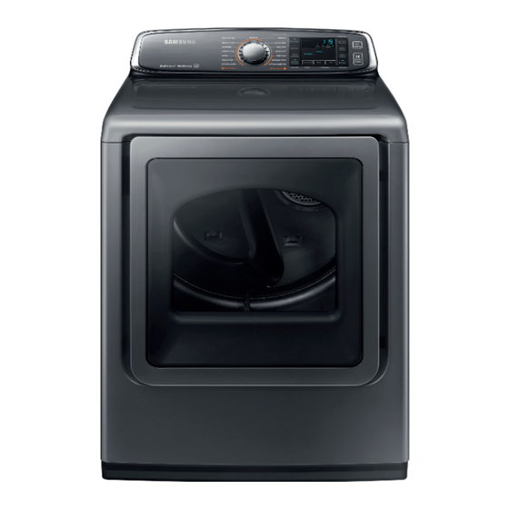
CLOTHES DRYER
CLOTHES DRYER
Basic Model
:
DV7400H
Model Name
:
DVE50M7450P
DVE50M7450W
DVG50M7450W
(DV7400M DRYER PROJECT)
Model Code
:
DVE50M7450P/AC
DVE50M7450W/A3
DVG50M7450W/A3
Manual
1. Safety Instructions
2. Features and
3. Disassembly and Reassembly
4. Troubleshooting
CONTENTS
Advertisement

Related Manuals for Samsung DV7400H


Summary of Contents for Samsung DV7400H
- Page 1 CLOTHES DRYER Basic Model DV7400H Model Name DVE50M7450P DVE50M7450W DVG50M7450W (DV7400M DRYER PROJECT) Model Code DVE50M7450P/AC DVE50M7450W/A3 DVG50M7450W/A3 SERVICE Manual CLOTHES DRYER CONTENTS 1. Safety Instructions 2. Features and 3. Disassembly and Reassembly 4. Troubleshooting...
- Page 2 This document can not be used without Samsung's authorization. 1. Safety InStructIonS 1-1. cautIon for Safety durIng ServIcIng 1. Do not allow the customer to repair the product. 4 The person may be injured or the product life may be shortened.
- Page 3 This document can not be used without Samsung's authorization. 1-2. Important Safety InformatIon To avoid risk of fire, electric shock, serious injury, or death when using your dryer, follow these basic precautions: 1. Read all instructions before using the dryer. 2. Install dryer according to Installation Instructions. Refer to the Grounding Instructions in the Installation Instructions for proper grounding of the dryer.
- Page 4 This document can not be used without Samsung's authorization. 22. Never operate the dryer with the guards and/or the panels removed. 23. Do not operate the dryer with missing or broken parts. 24. Do not bypass safety devices. 25. Keep area around the exhaust opening and adjacent surrounding areas free from accumulation of lint, dust, and dirt.
- Page 5 This document can not be used without Samsung's authorization. ■ gas dryer power supply This equipment MUST be grounded. In the event of an electrical short circuit, grounding reduces the risk of electric shock by providing an escape wire for the electrical current. This unit is equipped with a cord having a grounding wire with a grounding plug. The plug must be plugged into an outlet that is properly installed and grounded. Consult a qualified electrician or servicer if grounding instructions are not completely understood, or if doubt exists as to whether the equipment is properly grounded. Do not use an extension cord. If the product power cord is too short, have a qualified electrician install a three slot receptacle. This unit should be plugged into a separate 60 hertz circuit with the electrical rating as shown on the serial plate.
- Page 6 This document can not be used without Samsung's authorization. 2. FEATURES AND SPECIFICATIONS 2-1. FEATURES Features Description The largest capacity front-loading dryer, with a massive 7.4 cu. Ft. capacity, Largest Capacity ensures fewer loads and can handle extra large items easily, which means more “me time”.
- Page 7 This document can not be used without Samsung's authorization. 2-2. SPECIFICATIONS Type Front Loading Dryer Model Name DVE(G)52M745* Product-Inches (cm) 46.0 (116.8cm) A. Height Required for Installation - Inches 48.0 Product-Inches (cm) 27.0 (68.6) B. Width Required for Installation - Inches 29.0...
- Page 8 This document can not be used without Samsung's authorization. 2-3. Comparing Specifications With Existing Models Project DV7400H DV7400M Model DV48H7400W(P) DVE(G)50M7450W(P) Capacity (cu.ft / DOE) Power Resource Electric / Gas Electric / Gas Vent Sensor Vent Blockage Test Steam Smart Control...
- Page 9 This document can not be used without Samsung's authorization. 2-4. OPTIONS SPECIFICATIONS...
- Page 10 This document can not be used without Samsung's authorization. 3. Disassembly anD Reassembly 3-1. Tools foR Disassembly anD Reassembly Tool Type Remarks 14 mm Fan (1) Socket set with 6” extention 17 mm Roller Shaft (4) Wrench 8 mm Tool to fix the Roller Shaft on removing the nuts.
- Page 11 This document can not be used without Samsung's authorization. 3-2. sTanDaRD Disassembly DRawings To avoid risk of electrical shock, personal injury or death, disconnect the power to the Clothes Dryer. ► This is a standard disassembly diagram and may differ from the actual product.
- Page 12 This document can not be used without Samsung's authorization. Part figure Description 1. Remove the Panel Control. 2. Separate 4 Hook From the Guide PCB. main PCb Removal 3. Remove the Housings. 4. Remove 1 Screw from the Top Cover.
- Page 13 This document can not be used without Samsung's authorization. Part figure Description 1. Unplug the power cord. 2. Remove the four hinge screws from the door. 3. Remove the door by lifting it. 4. Remove the two screws from the holder-lever, and then remove the cover-holder.
- Page 14 This document can not be used without Samsung's authorization. Part figure Description 10. Remove the holder-glass. 11. Exchange the positions of: : The cover-hinge and handle door : The holder-hinge and guiderholder glass 12. Remove the Cover-Lever and then install it on the opposite side.
- Page 15 This document can not be used without Samsung's authorization. Part figure Description 1. Disconnect the power supply to the unit. 2. Remove the Panel Control, the Main PCB and the Cover Top. 3. Remove 3 screws from the Frame Front.
- Page 16 This document can not be used without Samsung's authorization. Part figure Description [Method of Door S/W disjointing] 1. After separate Holder Wire in Door S/W, Door S/W Hook Press and is Pull to Frame Front whole surface. frame front Removal 2.
- Page 17 This document can not be used without Samsung's authorization. Part figure Description 1. Disconnect the power supply to the unit. 2. Remove the Panel Control, the Main PCB, the Cover Top and the Frame Front. 3. Disconnect Interior Light wiring Harness.
- Page 18 This document can not be used without Samsung's authorization. Part figure Description 9. Remove the Duct Outlet. 10. Remove 3 screws from the Case Filter(F). 11. Remove 1 screw from the Case Filter(B). Make sure the Filter does not get damaged by the Roller.
- Page 19 This document can not be used without Samsung's authorization. Part figure Description 1. Disconnect the Power Supply to the unit. 2. Remove the Panel Control, the Main PCB, the Cover Top, the Frame Front and the Drum Front. 3. Remove Belt.
- Page 20 This document can not be used without Samsung's authorization. Part figure Description 1. Disconnect the power supply to the unit. 2. Remove the Panel Control, the Main PCB, the Cover Top, the Frame Front, the Drum Front and the Drum.
- Page 21 This document can not be used without Samsung's authorization. Part figure Description 1. Disconnect the power supply to the unit. 2. Remove the Panel Control, the Main PCB, the Cover Top, the Frame Front, the Drum Front and the Drum.
- Page 22 This document can not be used without Samsung's authorization. Part figure Description 8. Separate the Motor Assy at the Bottom Plate. 9. Remove 1 Nut Fan. CW to remove. CCW to assemble. 10. Remove the Fan. assy motor Removal (Continued) 11.
- Page 23 This document can not be used without Samsung's authorization. Part figure Description 14. Remove the Holder Shaft. assy motor Removal 15. Remove the Roller-Idler. 1. Disconnect the Power Supply to the unit. 2. Remove the Panel Control, the Main PCB, the Top.
- Page 24 This document can not be used without Samsung's authorization. Part Figure Description 1. After the knock-down to Motor/Assy-Motor, do the following. 2. Shut off gas supply. 3. Disconnect gas pipe. 4. Remove all the connectors. Burner Removal(Gas 5. Remove two screws (one at the front and the other Model) one at the back) securing Burner to Frame.
- Page 25 This document can not be used without Samsung's authorization. Part figure Description 1. Remove 3 screws from each Assy Base-stand. assy base-stand 2. Remove 2EA Assy Base-stand from Plate Bottom. Removal 3. Each Assy Base-stand Remove 2EA Leg. 24 _ Disassembly and Reassembly...
- Page 26 ACTION High temperature heating check • Clean the lint filter. • If this information code remains, contact a Samsung customer service center. (enter the line test mode) The electronic control needs to be checked. • Check if power is supplied properly.
- Page 27 This document can not be used without Samsung's authorization. 4-2. TEST MODE Continuous Run Mode ● Power On state Mixed Load Bell + Continuous Run Mode (Normal user mode) Dry Level 7 SEC Continuous Run Mode : 1. Press Mixed Load Bell + Dry Level for 7 sec during Power On State (Normal User Mode) .
- Page 28 This document can not be used without Samsung's authorization. Please follow below instruction for the trouble diagnosis and parts replacement. 1. As some electronic components can be damaged by static electricity from the resin part of dryer or the human body, remove the potential difference of the human body and the dryer by contacting the power plug before you start working at PCB.
- Page 29 This document can not be used without Samsung's authorization. Problem SOLUTION • Check the load for objects such as coins, loose buttons, nails, etc. Remove promptly. • It is normal to hear the dryer gas valve or heating element cycle on and off during the drying cycle.
- Page 30 This document can not be used without Samsung's authorization. 4-3. symPToms, diagnoses and acTions ● The power does not work. Set the input AC voltage. Neutral (Check AC 120/240V) Is the input AC Earth voltage normal? 120V 240V Directly connect the terminal block.
- Page 31 This document can not be used without Samsung's authorization. ● The drum does not work. Press the Start button. (Start/Pause is repeated) Is the Start button Close the door. (Check whether the door S/W is pressed) Is the door closed...
- Page 32 This document can not be used without Samsung's authorization. ● The clothes are not dried. Install the vent so that it is not blocked to the outside. (Check the exhaust hole) Is the vent properly installed? Clean the filter. (Check if there are any alien particles in...
- Page 33 This document can not be used without Samsung's authorization. ● The lamp does not work. Replace the door S/W. (Door operation of door S/W) Is the door S/W structurally on/off? Connect the power properly. Door open terminals COM to NC Less than Is the power 1 Ω...
- Page 34 This document can not be used without Samsung's authorization. There is an abnormal noise in the dryer. Reassemble the door seal. Do you hear a (Check the assembled condition of the door whistling sound from seal and check the door lever) the door seal? 1.
- Page 35 This document can not be used without Samsung's authorization. 4-4. comPonenT TesTing Procedures Warning To avoid risk of electrical shock, personal injury or death; disconnect power to dryer before servicing, unless testing requires power. ● component electrical testing (with ohmmeter) •...
- Page 36 This document can not be used without Samsung's authorization. ● centrifugal switch (motor) 2.88Ω between Pin# 3 and 4 3.5Ω between Pin# 4 and 5 ● gas model radiant sensor(10rs) • Resistance value < 1 Ω • If resistance is infinite, replace Radiant sensor...
- Page 37 This document can not be used without Samsung's authorization. ● sensor bars & temperature sensor check sensor bars Disconnect harness and test Pink wire Pin 4 to Orange wire Pin 5. • Approx ∞Ω without laundry • Approx 190Ω ± 10% with wet clothes cycling thermistor Disconnect harness and test Blue wire Pin 3 to Red wire Pin 6.
- Page 38 North & Latin America gspn3.samsungcsportal.com China china.samsungportal.com © 2024 Samsung Electronics Co.,Ltd. All This Service Manual is a property of Samsung Electronics Co.,Ltd. rights reserved. Any unauthorized use of Manual can be punished under applicable Printed in Korea International and/or domestic law.
Need help?
Do you have a question about the DV7400H and is the answer not in the manual?
Questions and answers