Advertisement
Quick Links
Advertisement

Subscribe to Our Youtube Channel
Related Manuals for ADC MGA1000 Series


Summary of Contents for ADC MGA1000 Series
- Page 1 MGA1000 MULTI-GAS ANALYSER OPERATION MANUAL...
- Page 2 2.10.1 Use of Gas Cylinders................... 13 2.10.2 Gas Leaks ....................14 2.10.3 Exhausting & Ventilation ................14 3. Setting Up.....................15 3.1 Preview....................... 15 3.2 On Power Up ....................... 15 3.3 Zero & Span Operations..................15 Copyright 2007, ADC Gas Analysis Ltd.
- Page 3 7.2.1 When set for voltage output ................30 7.2.2 When set for current output ................30 7.3 Alarm (Trip) Contacts ................... 30 7.4 Serial (RS 232) Port ..................... 31 8. Spare Parts ....................32 9. Notes......................33 Copyright 2007, ADC Gas Analysis Ltd.
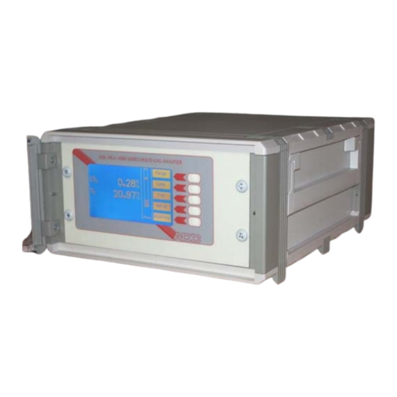
- Page 4 [refer to Section 2.9]. 1.1 About the Instrument The MGA1000 Series Instrument is designed for bench or rack mounting and provides a measurement of gas concentration according to specific user requirements. Single, dual or triple gas versions are available utilising one or more IRGA optical benches and/or chemical cells.
- Page 5 1.5 RS232 port An industry-standard serial port is fitted to the rear panel to allow gas readings to be read and zero to be set by a PC or other computer equipment. Copyright 2007, ADC Gas Analysis Ltd.
- Page 6 User. The IRGA bench is essentially an optical system and can suffer some deterioration in the performance if it is internally contaminated by the condition of the incoming gases. Copyright 2007, ADC Gas Analysis Ltd.
- Page 7 ADC (Sales & Service) Ltd. or their authorised local agents can supply replacement sensors with the correct fittings and electrical characteristics. Fitting alternative parts may cause problems and will invalidate the instrument warranty.
- Page 8 In all cases the ambient conditions must comply with the specifications. High ambient conditions will affect reliability. IMPORTANT: The MGA series analysers are not certified for operation in hazardous environments. Copyright 2007, ADC Gas Analysis Ltd.
- Page 9 If the front, top or bottom sections of the enclosure are removed, BEWARE of HIGH VOLTAGES near the power connector, switch and internal supply. • When REMOVING or REPLACING the enclosure sections ALWAYS disconnect the mains supply FIRST. Copyright 2007, ADC Gas Analysis Ltd.
- Page 10 Route signal cables well away from power cables, switchgear and other noise sources. For long cable runs, and in electrically noisy environments, optical RS232C cable extenders are recommended. Contact ADC (Spares & Service) Ltd. or their local authorised agents for advice. 2.5 Analogue Outputs Analogue outputs are provided for connection to chart recorders, remote meters, analogue logging equipment etc.
- Page 11 3. Remove the top cover from the instrument by undoing the six screws on the top face, and two screws on the back edge of the cover plate. Lift the cover clear. Copyright 2007, ADC Gas Analysis Ltd.
- Page 12 Alarm contact outputs are available via a 14 way Amphenol connector on the rear panel. A suitable connector is provided in the kit with each instrument, and further supplies are available from ADC (Spares & Service) Ltd. or their authorised local agent. The connector pin functions are printed on the rear panel adjacent to the connector, and the pin numbering scheme is shown in Fig 4.
- Page 13 Unless the gas is perfectly clean and dry, particulate filters and / or driers must be fitted externally. Contact ADC (Spares & Service) Ltd. or their authorised local agents for advice. The requirements for particular gases vary with the application and therefore these and the gas circuit are specific to the delivered Instrument.
- Page 14 Exhaust Ducts, Chimneys, etc. In most respects fresh air should be treated in the same way as the sample gas with regard to filtering, moisture content etc. See span gas, section 2.7.3. Copyright 2007, ADC Gas Analysis Ltd.
- Page 15 An indicating form of calcium sulphate (CaSO ) known as 'DRIERITE' is normally supplied with new instruments and replacement supplies are available from ADC (Spares & Service) Ltd or their local authorised agents. In use, drierite changes from blue to pink as it becomes exhausted, making it obvious when the container should be refilled with fresh chemical.
- Page 16 Under normal use, the quantity supplied will last for about 6 months to a year. Replacements can be obtained from ADC (Spares & Service) Limited who will also advise on the use of chemicals obtainable by the User.
- Page 17 If Span cylinders contain hazardous or inflammable gases, they must carry suitable warning labels, and if inflammable, must be located in a suitable ‘Inflammable Store’ when in use or in storage. In all cases the local safety regulations must be consulted and followed. Copyright 2007, ADC Gas Analysis Ltd.
- Page 18 'How often' to Zero or Span varies with each instrument. The interval required depends on how much re-adjustment is being carried out: this can be established by noting the discrepancy of the displayed value prior to resetting. Copyright 2007, ADC Gas Analysis Ltd.
- Page 19 To adjust the contrast, Select the following menu functions: Display The contrast screen is displayed. Use the Figure 6 - screen contrast adjustment lighter and darker controls to get the best display. The bar shows the amount of Copyright 2007, ADC Gas Analysis Ltd.
- Page 20 For example, pressing the function key 'Zero adj' on the main menu, presents a Sub-menu with the function keys on the right hand side of the display and instructions on the bottom of the screen. Copyright 2007, ADC Gas Analysis Ltd.
- Page 21 If there is no reading shown under this column on the display, or if the ‘Off’ key is used when setting the low point, this trip will not respond to low readings. Copyright 2007, ADC Gas Analysis Ltd.
- Page 22 3.7.2 Serial Port Settings The serial port is configured from the front panel. To check or change the serial port settings, select: Ser. Port From the main screen menu. The screen will show current settings. Copyright 2007, ADC Gas Analysis Ltd.
- Page 23 The gas ranges, display format and units of measurement are factory set to order, and no changes are possible. If changes to ranges or gases are required, contact ADC (Sales & Service) Ltd. or their local authorised agents for a quotation.
- Page 24 Note: because the instructions will vary slightly from gas to gas, the instructions given here are fairly general. ADC (Spares & Service) Ltd. or their authorised local agent will be pleased to answer any questions.
- Page 25 Zero, but the processor will automatically reset the gas reading to Zero. Auto zero will attempt adjustment for all gases, but will not initiate a coarse zero adjustment if the standard zero fails. Copyright 2007, ADC Gas Analysis Ltd.
- Page 26 If possible, verify the gas concentration on a second analyser, or try another bottle of span gas. If the span fails and the span gas is correct, contact ADC (Spares & Service) Ltd., or their local authorised agents for service.
- Page 27 (down to 1O microns) and the filter elements regularly replaced. Where dust has penetrated the instrument, arrange for a service visit so that the optics can be cleaned and full performance restored. Copyright 2007, ADC Gas Analysis Ltd.
- Page 28 If necessary, adjust the flow using the pump speed control (RV2 on the power supply board) or sample throttle (when fitted). If the flow continues to fall off over a period of time, it may indicate that the lines are becoming blocked, as indicated in the previous section. Copyright 2007, ADC Gas Analysis Ltd.
- Page 29 Gas Circuit. These paths can also become affected by blockages and they (or some other reason) may require some re-adjustment. Readjustment is not a routine procedure – always check span and zero gas bottles, regulator pressures etc. before attempting adjustment. Copyright 2007, ADC Gas Analysis Ltd.
- Page 30 See section 4. Lens Window Window Detector Analysis Cell Source Motor Optical Filter Gas Entries Lens Sensor Filter Wheel Figure 13 The Gas Correlation optical bench Copyright 2007, ADC Gas Analysis Ltd.
- Page 31 This rotates at 200RPM to give 3.3Hz modulation of the IR beam, which passes through the cell, and onto a solid state detector, via a suitable thin film optical filter in close proximity. Copyright 2007, ADC Gas Analysis Ltd.
- Page 32 (absorption). The instrument automatically compensates for variations in output by adjustments made during zero and span cycles. Failure of either adjustment can be due to a source or detector problem. Copyright 2007, ADC Gas Analysis Ltd.
- Page 33 30V DC / AC peak Max. voltage with respect to chassis: 30V DC / AC peak Auxiliary 24V output: 24V DC ± 20% at 500mA maximum. Auxiliary supply has negative rail connected to chassis. Copyright 2007, ADC Gas Analysis Ltd.
- Page 34 MGA1000 Multi-Gas Analyser Operation Manual Iss. 1.00 7.4 Serial (RS 232) Port The port signal levels correspond nominally to RS232C specifications; however the output is approximately ± 9V into 7kΩ. Copyright 2007, ADC Gas Analysis Ltd.
- Page 35 8. S PARE ARTS The following table lists some of the more common spare parts. ADC (Spares & Service) Limited provided total parts support and can quote for any item not listed – just contact us or our authorised local agent.
- Page 36 MGA1000 Multi-Gas Analyser Operation Manual Iss. 1.00 9. N OTES (Use this page to record notes about your instrument) Copyright 2007, ADC Gas Analysis Ltd.
- Page 38 ADC Gas Analysis Ltd or its distributor will accept old analysis units before 2005 but retain the right to charge their disposal unless the unit is being replaced by new equipment.
- Page 39 Authorised Local Agent: ADC Gas Analysis Limited Unit 35 Hoddesdon Industrial Centre Pindar Road, Hoddesdon Herts, EN11 0FF United Kingdom Tel: +44-1992 478600 Fax: +44-1992 478938 Email: sales@adc-analysers.com Web: http://www.adc-gas.com...
Need help?
Do you have a question about the MGA1000 Series and is the answer not in the manual?
Questions and answers