Advertisement
Available languages
Available languages
Quick Links
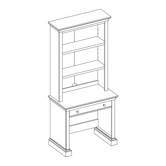
Canton Writing Desk with Hutch
If you have any questions regarding assembly or if parts are missing, DO NOT return this item to the
store where it was purchased. Please call our customer service number and have your instructions and
parts list ready to provide the model name, part name or factory number:
Pacific Standard Time: 8:30 a.m. - 4:30 p.m., Monday - Friday
Or visit our web site 24 hours a day, 7 days a week for product assistance at
THIS INSTRUCTION BOOKLET CONTAINS IMPORTANT SAFETY INFORMATION.
Stock # BHS336158813015
ADULT ASSEMBLY REQUIRED
1-866-942-5362
www.whalenstyle.com
Or e-mail your request to parts@whalenfurniture.com
PLEASE READ AND KEEP FOR FUTURE REFERENCE.
Date 2023-04-15
LOT NUMBER:
DATE PURCHASED:
Rev. 0001-A
/
/
Advertisement

Subscribe to Our Youtube Channel
Related Manuals for Better Homes and Gardens Canton BHS336158813015


Summary of Contents for Better Homes and Gardens Canton BHS336158813015
- Page 1 LOT NUMBER: DATE PURCHASED: Canton Writing Desk with Hutch Stock # BHS336158813015 ADULT ASSEMBLY REQUIRED If you have any questions regarding assembly or if parts are missing, DO NOT return this item to the store where it was purchased. Please call our customer service number and have your instructions and parts list ready to provide the model name, part name or factory number: 1-866-942-5362 Pacific Standard Time: 8:30 a.m.
- Page 2 M A X I M U M R E C O M M E N D E D W E I G H T L O A D S MANUFACTURER: Whalen Furniture Manufacturing CATALOG: Canton Writing Desk with Hutch MODEL # BHS336158813015 MAXIMUM LOAD 13.6 kg / 30 lb.
- Page 3 IMPORTANT Before you begin: Open, identify and count all parts prior to assembly. Lay out parts on a flat and non-abrasive surface. You will need the parts identified on page 4 and 5 of this instruction manuals. NOTE: IT IS VERY IMPORTANT TO USE GLUE WITH DOWELS. EXCESS GLUE CAN BE WIPED OFF WITH DAMP CLOTH.
- Page 4 Parts and Hardware List Please read completely through the instructions and verify that all listed parts and hardware are present before beginning assembly. A- Desk Top B- Left Side Frame C- Right Side Frame (Qty. 1) (Qty. 1) (Qty. 1) D- Upper Modesty Panel E- Lower Modesty Panel F- Crossbar...
- Page 5 Parts and Hardware List Please read completely through the instructions and verify that all listed parts and hardware are present before beginning assembly. S- Hutch Lower Back Stretcher T- Hutch Top Front Molding U- Hutch Back Panel (Qty. 1) (Qty. 1) (Qty.
- Page 6 Assembly Instructions ③ x 6 NOTE: Please do not fully tighten all cam locks and screws until you finish assembling all parts. Once assembled, go back and fully tighten all cam locks and screws. This will make the assembly easier. 1.
- Page 7 Assembly Instructions Grooves line up with each other and face inward ① x 4 3. Align and attach the Drawer Side Panels (I and J) to the Drawer Front (G) by engaging 4 Small Cam Locks (1). (Refer to page 3 on Cam Lock system operation supplement).
- Page 8 Assembly Instructions The cam lock housings face outward. ① x 2 4. Orient and attach the Drawer Bottom Support (K) to the Drawer Front (G) with two 2 Cam Locks (1).
- Page 9 Assembly Instructions 5. Slide the Drawer Bottom Panel (L) into the grooves on both Drawer Side Panels (I and J) until fully inserted into the Drawer Front Panel (G).
- Page 10 Assembly Instructions Groove ⑦ x 6 6. Fasten the Drawer Back Panel (H) between the Drawer Side Panels (I and J) with four 30 mm Screws (7). Make sure that the Drawer Bottom Panel (L) fits into the groove on the Drawer Back Panel (H) properly. 7.
- Page 11 Assembly Instructions ⑧ x 2 ⑨ x 2 8. Install two Knobs (8) to the front of Drawer Front (G) with two 22 mm Bolts (9).
- Page 12 Assembly Instructions ③ x 18 9. Securely screw the Cam Bolts (3) into the designated small holes on the Desk Top (A) and Desk Side Frames (B and C) using a Phillips Screwdriver.
- Page 13 Assembly Instructions ④ x 16 10. Glue the Wood Dowels (4) into the inner holes on the Desk Side Frames (B and C), Modesty Panels (D and E) and Crossbar (F) as shown. NOTE: It is very important to use a small amount of glue on both ends of dowels and wipe away the excess glue immediately with a damp cloth.
- Page 14 Assembly Instructions The cam lock housings face outward and are located at up. The cam lock housings face inward. The cam lock housings face outward. D/E/F ② x 12 11. Orient and attach the Modesty Panels (D and E) and Crossbar (F) to the Desk Left Side Frame (B) by engaging 6 Large Cam Locks (2).
- Page 15 Assembly Instructions Pilot holes for metal brackets. B/C/D ② x 2 13. Place the Desk Top (A) onto the inserted wood dowels properly and secure the Desk Top (A) to the Upper Modesty Panel (D) by engaging 2 Large Cam Locks (2).
- Page 16 Assembly Instructions ② x 4 14. Fasten the Desk Top (A) to the Desk Side Frames (B and C) with 4 Large Cam Locks (2).
- Page 17 Assembly Instructions ③ x 16 15. Securely screw the Cam Bolts (3) into the designated small holes on the Hutch Top (M), Hutch Side Panels (N and O) and Hutch Side Moldings (P) using a Phillips Screwdriver.
- Page 18 Assembly Instructions ④ x 16 16. Glue the Wood Dowels (4) into the designated holes on the Hutch Side Panels (N and O), Stretchers (R and S) and Hutch Top Front Molding (T) as shown.
- Page 19 Assembly Instructions The outer edges are even. ② x 6 17. Align and attach the Hutch Side Moldings (P) to the Hutch Side Panels (N and O) with 3 Large Cam Locks (2) in each. Make sure that the outer edges are flush with each other.
- Page 20 Assembly Instructions ⑦ x 3 18. Using the pilot holes as a guide, fasten the Hutch Top Front Molding (T) to the Hutch Top (M) using three 30 mm Screws (7).
- Page 21 Assembly Instructions Wood dowels The cam lock housing face outward. ② x 4 19. Orient and align the Hutch Back Stretchers (R and S) to the Hutch Left Side Panel (N) with 2 Large Cam Locks (2) 20. Repeat the same procedure to attach the Hutch Right Side Panel (O) at the opposite end.
- Page 22 Assembly Instructions N/O/R ② x 6 21. Align and attach the Hutch Top (M) to the Hutch Side Panels (N and O) and Hutch Upper Back Stretcher (R) by engaging 6 Large Cam Locks (2).
- Page 23 Assembly Instructions The adhesive tape faces outward. ⑥ x 22 22. Now, go back and securely tighten all the cam locks and screws. Make sure that all the parts are tight and there are no gaps between the parts. This will help keep the unit square. 23.
- Page 24 Assembly Instructions ⑤ x 8 NOTE: The Metal Brackets are provided to prevent the Hutch from falling over, please make sure you attach them to the Base with all the 12 mm Screws (5). 24. Ask for assistance to place the assembled Hutch on the top of the desk carefully, so that you will not scratch the top surface.
- Page 25 Assembly Instructions ⑩ x 8 26. Insert eight Shelf Supports (10) into the holes at your desired height inside the Hutch. Make sure you place the four Shelf Supports (10) at the same level to level the shelf. 27. Tilt and rest the Adjustable Shelves (Q) onto the Shelf Supports (10).
- Page 26 Assembly Instructions Release leveler Ball bearing cart FRONT FRONT Ball bearing cart Drawer Installation 28. Insert the assembled Drawer to the frame. Extend the Ball Bearing Slide Tracks on the unit all the way forward (including ball bearing cart). Then align the Slide Runners on the assembled drawer with the Slide Tracks and push the drawer carefully inside until it stops.
- Page 27 Assembly Instructions x 12 29. Plug the Cam Lock Covers (12) onto the visible cam locks to conceal the cams.
- Page 28 Assembly Instructions Wooden stud Wall Short screw Nylon strap Wall Long screw Metal bracket Floor leveler Tools required (not included): Phillips screwdriver, stud finder, tape measure, pencil, power drill and 1/8” drill bit. 30. Ask assistance to position the assembled unit at the desired location and adjust the pre-attached floor levelers to level the unit against a wall.
- Page 29 FURNITURE TIPPING RESTRAINT YOUNG CHILDREN MAY BE INJURED BY TIPPING FURNITURE AND YOU MUST USE THIS TIPPING RESTRAINT TO ATTACH THIS UNIT TO THE WALL, TO PREVENT ACCIDENTS AND/OR INJURIES. THIS HARDWARE, MUST BE PROPERLY INSTALLED (FOLLOW ALL DIRECTIONS IN ORDER ON THIS INSTRUCTIONS), TO PROVIDE PROTECTION AGAINST THE UNEXPECTED TIPPING OF FURNITURE DUE TO IMPROPER USE.
- Page 30 Care and Maintenance Use a soft, clean cloth that will not scratch the surface when dusting. Use of furniture polish is not necessary. Should you choose to use polish, test first in an inconspicuous area. Using solvents of any kind on your furniture may damage your furniture’s finish. ...
- Page 31 NÚMERO de LOTE:__________ FECHA de COMPRA: Escritorio Canton con gabinete superior Modelo # BHS336158813015 ENSAMBLE REQUERIDO POR ADULTO Si tienen alguna pregunta acerca del ensamble o si alguna parte está faltante, no retorne esté producto a la tienda donde lo compro. Por favor llame a nuestro departamento de ayuda al cliente teniendo su instructivo y lista de partes para proveer el modelo, nombre de parte o el número de fábrica: 1-866-942-5362 Hora estándar del Pacífico: 8:30 a.m.
- Page 32 M Á X I M O P E S O R E C O M E N D A D O FABRICANTE: Whalen Furniture Manufacturing CATALOGO : Escritorio Canton con gabinete superior MODELO # BHS336158813015 CARGA MÁXIMA 13.6 kg / 30 lb. CARGA MÁXIMA 45.4 kg / 100 lb.
- Page 33 IMPORTANTE Antes de comenzar: Abra, identifique y cuente todas las partes antes del ensamble. Coloque las piezas sobre una superficie plana y no abrasiva. Tendrá que las partes identificadas en la página 4 y 5 de este manual de instrucciones. NOTA: ES MUY IMPORTANTE PARA EL USO DE PEGAMENTO CON LAS CLAVIJAS DE MADERA.
- Page 34 Lista de partes y material de ferretería Por favor lea completamente las instrucciones y verifique que estén todas las partes y partes de ferretería antes de iniciar el ensamblado. A- Tapa del escritorio B- Marco izquierdo C- Marco derecho (Cant. 1) (Cant.
- Page 35 Lista de partes y material de ferretería Por favor lea completamente las instrucciones y verifique que estén todas las partes y partes de ferretería antes de iniciar el ensamblado. S- Soporte inferior posterior del gabinete T- Moldura superior frontal del gabinete U- Panel posterior del gabinete (Cant.
- Page 36 Instrucciones de ensamble ③ x 6 NOTA: Por favor no apriete completamente todos los pernos y tuercas de fijación, hasta que termine con el ensamble de las partes. Después asegúrese de apretar todos los pernos y las tuercas de fijación. Esto hará...
- Page 37 Instrucciones de ensamble Las ranuras e alinean la unas con las otras y apuntan hacia adentro ① x 4 3. Alinear y adjuntar los paneles laterales del cajón (I y J) al frente del cajón (G) empleando 4 tuercas de fijación pequeñas (1).
- Page 38 Instrucciones de ensamble Los espacios de las tuercas de fijación apuntan hacia afuera. ① x 2 4. Orientar y adjuntar el soporte inferior del cajón (K) al frente del cajón (G) con 2 tuercas de fijación pequeñas (1).
- Page 39 Instrucciones de ensamble 5. Deslizar el panel inferior del cajón (L) en las ranuras en ambos paneles laterales del cajón (I y J) hasta insertar completamente en el panel frontal del cajón (G).
- Page 40 Instrucciones de ensamble Ranura ⑦ x 6 6. Sujetar el panel posterior del cajón (H) entre los paneles laterales del cajón (I y J) con 4 pernos de 30 mm (7). Asegurar de que el panel inferior del cajón (L) encaje en las ranuras en el panel posterior del cajón (H). 7.
- Page 41 Instrucciones de ensamble ⑧ x 2 ⑨ x 2 8. Instalar 2 perillas (8) a la parte frontal del frente del cajón (G) con 2 pernos de 22 mm (9).
- Page 42 Instrucciones de ensamble ③ x 18 9. Atornillar los pernos de fijación (3) en los agujeros pequeños designados en la tapa del escritorio (A) y en los marcos laterales del escritorio (B y C) usando el desarmador estrella.
- Page 43 Instrucciones de ensamble ④ x 16 10. Pegar las clavijas de madera (4) en los espacios interiores en los marcos laterales del escritorio (B y C), en los paneles modestia (D y E) y en el soporte (F) como se muestra. NOTA: Es importante usar una cantidad pequeña de pegamento en ambos lados de las clavijas y limpiar el exceso de pegamento inmediatamente con una toalla húmeda.
- Page 44 Instrucciones de ensamble Los espacios de las tuercas de fijación apuntan hacia afuera y están arriba. Los espacios de las tuercas de fijación apuntan hacia adentro. Los espacios de las tuercas de fijación D/E/F apuntan hacia afuera. ② x 12 11.
- Page 45 Instrucciones de ensamble Los agujeros pilotos para los soportes de metal. B/C/D ② x 2 13. Poner la tapa del escritorio (A) sobre las clavijas de madera insertadas y asegurar la tapa del escritorio (A) al panel modestia superior (D) empleando 2 tuercas de fijación grande (2).
- Page 46 Instrucciones de ensamble ② x 4 14. Sujetar la tapa del escritorio (A) a los marcos laterales del escritorio (B y C) con 4 tuercas de fijación grandes (2).
- Page 47 Instrucciones de ensamble ③ x 16 15. Apretar los pernos de fijación (3) en los agujeros pequeños designados en la tapa del gabinete (M), en los paneles laterales del gabinete (N y O) y en las molduras laterales del gabinete (P) usando el desarmador estrella.
- Page 48 Instrucciones de ensamble ④ x 16 16. Pegar las clavijas de madera (4) en los agujeros pequeños designados en los paneles laterales del gabinete (N y O), en los soportes (R y S) y en la moldura superior frontal del gabinete (T) como se muestra.
- Page 49 Instrucciones de ensamble Los bordes exteriores estan nivelados. ② x 6 17. Alinear y adjuntar las molduras laterales del gabinete (P) a los paneles laterales del gabinete (N y O) con 3 tuercas de fijación grandes (2) en cada una. Asegurar de que los bordes exteriores estén nivelados los unos con los otros.
- Page 50 Instrucciones de ensamble ⑦ x 3 18. Usando los agujeros pilotos como guía, sujetar la moldura superior frontal del gabinete (T) a la tapa del gabinete (M) usando 3 pernos de 30 mm (7).
- Page 51 Instrucciones de ensamble Clavijas de madera Los espacios de las tuercas de fijación apuntan hacia afuera. ② x 4 19. Orientar y alinear los soportes posteriores del gabinete (R y S) al panel izquierdo del gabinete (N) con 2 tuercas de fijación grandes (2) 20.
- Page 52 Instrucciones de ensamble N/O/R ② x 6 21. Alinear y adjuntar la tapa del gabinete (M) a los paneles laterales del gabinete (N y O) y al soporte superior posterior del gabinete (R) empleando 6 tuercas de fijación grande (2).
- Page 53 Instrucciones de ensamble La cinta adhesiva apunta hacia afuera. ⑥ x 22 22. Ahora, volver y apretar todas las tuercas de fijación y los pernos. Asegurar que todas las partes estén apretadas y de que no hay huecos entre las partes. Esto ayudara a mantener la unidad cuadrada. 23.
- Page 54 Instrucciones de ensamble ⑤ x 8 NOTA: Los soportes de metal estan provistos para prevenir de que el gabinete se caiga, por favor asegúrese de adjuntarlos a la base con todos los pernos de 12 mm (5). 24. Pedir asistencia para poner el gabinete ensamblado sobre la tapa del escritorio, para que no raye la superficie superior.
- Page 55 Instrucciones de ensamble ⑩ x 8 26. Insertar 8 soportes para repisa (10) en los aguejros a la altura deseada dentro del gabinete. Asegurar de poner 4 soportes para repisa (10) en el mismo nivel para nivela la repisa. 27. Inclinar y descansar las repisas ajustables (Q) sobre los soportes para repisa (10).
- Page 56 Instrucciones de ensamble Palanca de liberación Carrito de baleros FRENTE FRENTE Carrito de baleros Instalación del cajón 28. Insertar el cajón ensamblado en el marco. Extender los carriles de la corredera de baleros en los paneles todo el camino hacia enfrente (incluyendo el carrito de baleros). Luego alinear los complementos de corredera en el cajón ensamblado con los carriles de corredera y empujar el cajón hacia adentro hasta que tope.
- Page 57 Instrucciones de ensamble x 12 29. Enchufar las tapas de las tuercas de fijación (12) sobre las tuercas de fijación visibles para esconder.
- Page 58 Instrucciones de ensamble Viga de madera Pared Perno chico Correa de Pared Nylon Perno largo Soporte de metal Nivelador de piso Herramientas requeridas (no provistas): Desarmador estrella, buscador de vigas, lápiz, cinta métrica, taladro y broca de 1/8 pulgadas 30. Poner la unidad ensamblado en el lugar deseado y ajustar los niveladores de piso para nivelar la unidad contra la pared.
- Page 59 SISTEMA DE RESTRICCIÓN DE MOVIMIENTO NIÑOS PEQUEÑOS PUEDEN RESULTAR LASTIMADOS POR MUEBLES INCLINADOS Y DEBE INSTALAR EL JUEGO DE RESTRICCIÓN DE MOVIMIENTO CON LA UNIDAD EN FUNCIÓN, PARA PREVENIR LA INCLINACIÓN DE LA UNIDAD, CAUSANDO CUALQUIER ACCIDENTE O DAÑO. ESTÉ JUEGO DEBE SE INSTALADO CORRECTAMENTE (SIGA LAS DIRECCIÓN EN ORDEN DE LAS INSTRUCCIONES), PARA PROVEER PROTECCIÓN EN CONTRA DE LA INCLINACIÓN INESPERADA DEL MUEBLE DEBIDO AL USO INAPROPIADO.
- Page 60 Mantenimiento y cuidados Use una toalla suave y limpia para evitar daños y rayaduras. Uso de cera para pulir muebles no es necesario. Si desea usar cera cheque en un área que no sea visible para revisar su funcionamiento. ...
Need help?
Do you have a question about the Canton BHS336158813015 and is the answer not in the manual?
Questions and answers