Advertisement
Available languages
Available languages
Quick Links
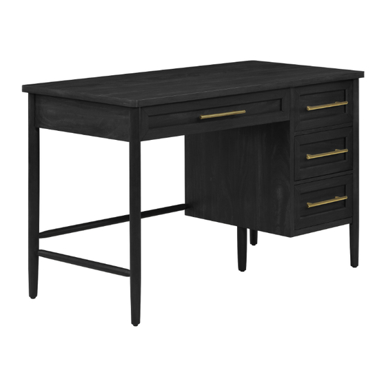
Black Wood Grain Desk with Brass Pulls
If you have any questions regarding assembly or if parts are missing, DO NOT return this item to the
store where it was purchased. Please call our customer service number and have your instructions
and parts list ready to provide the model name, part name or factory number:
Or visit our web site 24 hours a day, 7 days a week for product assistance at
THIS INSTRUCTION BOOKLET CONTAINS IMPORTANT SAFETY INFORMATION.
Stock # BHS336158813033
ADULT ASSEMBLY REQUIRED
Pacific Standard Time: 8:30 a.m. - 4:30 p.m., Monday - Friday
Or e-mail your request to parts@whalenfurniture.com
PLEASE READ AND KEEP FOR FUTURE REFERENCE.
Date 2023-03-31
866-942-5362
www.whalenstyle.com
Rev. 0001-A
LOT NUMBER:
DATE PURCHASED:
/
/
Advertisement

Related Manuals for Better Homes and Gardens Oaklee BHS336158813033


Summary of Contents for Better Homes and Gardens Oaklee BHS336158813033
- Page 1 LOT NUMBER: DATE PURCHASED: Black Wood Grain Desk with Brass Pulls Stock # BHS336158813033 ADULT ASSEMBLY REQUIRED If you have any questions regarding assembly or if parts are missing, DO NOT return this item to the store where it was purchased. Please call our customer service number and have your instructions and parts list ready to provide the model name, part name or factory number: 866-942-5362 Pacific Standard Time: 8:30 a.m.
- Page 2 M A X I M U M R E C O M M E N D E D W E I G H T L O A D S MANUFACTURER: Whalen Furniture Manufacturing CATALOG: Black Wood Grain Desk with Brass Pulls MODEL # BHS336158813033 MAXIMUM LOAD 200 lb.
- Page 3 IMPORTANT Before you begin: Open, identify and count all parts prior to assembly. Lay out parts on a flat and non- abrasive surface. You will need the parts identified on page 4 and 5 of this instruction manuals. NOTE: IT IS VERY IMPORTANT TO USE GLUE WITH DOWELS. EXCESS GLUE CAN BE WIPED OFF WITH DAMP CLOTH.
- Page 4 Parts and Hardware List Please read completely through the instructions and verify that all listed parts and hardware are present before beginning assembly. A- Desk Top (Qty. 1) B- Left Side Frame (Qty. 1) C- Right Side Frame (Qty. 1) D- Partition Panel (Qty.
- Page 5 Parts and Hardware List Please read completely through the instructions and verify that all listed parts and hardware are present before beginning assembly. P- Large Drawer Bottom Support Q- Large Drawer Bottom Panel R- Small Drawer Front (Qty. 1) (Qty. 1) (Qty.
- Page 6 Assembly Instructions ③ x 18 NOTE: Please do not fully tighten all cam locks and screws until you finish assembling all parts. Once assembled, go back and fully tighten all cam locks and screws. This will make the assembly easier. 1.
- Page 7 Assembly Instructions Grooves line up with each other and face inward. ① x 4 3. Align and attach the Large Drawer Side Panels (N and O) to the Large Drawer Front (L) by engaging four Small Cam Locks (1). (Refer to page 3 on Cam Lock system operation supplement).
- Page 8 Assembly Instructions The cam lock housings face outward. ① x 2 4. Orient and attach the Large Drawer Bottom Support (P) to the Large Drawer Front (L) with two Small Cam Locks (1).
- Page 9 Assembly Instructions 5. Slide the Large Drawer Bottom Panel (Q) into the grooves on both Large Drawer Side Panels (N and O) until fully inserted into the Large Drawer Front (L).
- Page 10 Assembly Instructions Groove ⑥ x 6 6. Fasten the Large Drawer Back Panel (M) between the Large Drawer Side Panels (N and O) with four 30 mm Screws (6). Make sure that the Large Drawer Bottom Panel (Q) fits into the groove on the Large Drawer Back Panel (M) properly.
- Page 11 Assembly Instructions ⑧ x 2 8. Install one Handle (W) to the front of Large Drawer Front (L) with two 22 mm Bolts (8).
- Page 12 Assembly Instructions Grooves line up with each other and face inward. ① x 12 9. Align and attach two Small Drawer Side Panels (T and U) to one Small Drawer Front Panel (R) by engaging four Small Cam Locks (1).
- Page 13 Assembly Instructions 10. Slide one Small Drawer Bottom Panel (V) into the grooves on both Small Drawer Side Panels (T and U) until fully inserted into the Small Drawer Front (R).
- Page 14 Assembly Instructions Groove ⑥ x 12 11. Fasten one Small Drawer Back Panel (S) between the Small Drawer Side Panels (T and U) with four 30 mm Screws (6). Make sure that the Small Drawer Bottom Panel (V) fits into the groove on the Small Drawer Back Panel (S) properly.
- Page 15 Assembly Instructions ⑧ x 6 12. Install one Handle (W) to the front of the Small Drawer Front (R) with two 22 mm Bolts (8). 13. Repeat the previous steps to assemble two additional Small Drawers.
- Page 16 Assembly Instructions ③ x 12 14. Securely screw the Cam Bolts (3) into the designated small holes on the Right Side Frame (C) and the Partition Panel (D) using a Phillips screwdriver.
- Page 17 Assembly Instructions ④ x 20 15. Glue the Wood Dowels (4) into the inner holes on the Panels (C, D, E and I) and two Crossbars (J) as shown. NOTE: It is very important to use a small amount of glue on both ends of dowels and wipe away the excess glue immediately with a damp cloth.
- Page 18 Assembly Instructions The cam lock housing face inward. ⑦ x 2 16. Using the inserted wood dowels as a guide, attach the Cabinet Bottom Panel (I) to the Cabinet Back Panel (E) with two 50 mm Screws (7).
- Page 19 Assembly Instructions ② x 4 17. Align and attach the previous assembly to the Right Side Frame (C) by engaging four Large Cam Locks (2).
- Page 20 Assembly Instructions The cam lock faces the bottom panel. ② x 2 18. Orient and attach two Crossbars (J) to the Right Side Frame (C) by engaging two Large Cam Locks (2).
- Page 21 Assembly Instructions ② x 6 19. Repeat the same procedure to attach the Partition Panel (D) at the opposite end.
- Page 22 Assembly Instructions Floor leveler Remove the plastic cap 20. Remove the plastic cap from the hanger bolt of the Support Leg (K). 21. Securely screw the Support Leg (K) into the threaded hole on the Cabinet Bottom Panel (I). Set the floor leveler to correct height.
- Page 23 Assembly Instructions ③ x 4 22. Securely screw the Cam Bolts (3) into the designated small holes on the Partition Panel (D) using a Phillips screwdriver.
- Page 24 Assembly Instructions ③ x 15 23. Securely screw the Cam Bolts (3) into the designated small holes on the Desk Top (A) and Left Side Frame (B) using a Phillips screwdriver.
- Page 25 Assembly Instructions ④ x 8 24. Glue the Wood Dowels (4) into the inner holes on the Left Side Frame (B) and Left Stretchers (F and G) as shown.
- Page 26 Assembly Instructions The cam lock housing face inward and are located at top. ② x 2 25. Orient and attach the Left Back Stretcher (F) to the Left Side Frame (B) by engaging two Large Cam Locks (2) as shown.
- Page 27 Assembly Instructions Pilot holes for metal bracket ② x 2 26. Orient and attach the Left Front Stretcher (G) to the Left Side Frame (B) by engaging two Large Cam Locks (2).
- Page 28 Assembly Instructions ⑤ x 5 ⑨ x 1 27. Using the pilot holes as a guide, align and attach the Metal Bracket (9) at the joint where the Left Front Stretcher (G) meets the Left Side Frame (B) with five 12 mm Screws (5).
- Page 29 Assembly Instructions The slant holes will face the floor when the unit is turned upright. ② x 4 28. Insert the tenon of the Bottom Back Stretcher (H) into the mortise of the Left Side Frame (B). 29. Align and attach the previous assembly to the assembled Partition Panel (D) by engaging four Large Cam Locks (2).
- Page 30 Assembly Instructions ⑦ x 2 30. Insert and screw two 50 mm Screws (7) into the slant holes on the Bottom Back Stretcher (H). Tighten the screws with a Phillips screwdriver (not provided).
- Page 31 Assembly Instructions ② x 11 31. Ask for assistance to stand the previous assembly upright and position it near the desired location. 32. Align the large holes on the Desk Top (A) over the inserted wood dowels and press them together. Secure the top panel into place by engaging eleven Large Cam Locks (2).
- Page 32 Assembly Instructions Ball bearing cart FRONT Ball bearing cart FRONT Drawer installation 33. Insert the assembled drawers to the frames. Extend the Ball Bearing Slide Tracks on the unit all the way forward (including ball bearing cart). Then align the Slide Runners on the assembled drawer with the Slide Tracks and push the drawer carefully inside until it stops.
- Page 33 Assembly Instructions Floor leveler 34. If necessary, adjust the pre-attached floor levelers to level the unit.
- Page 34 Care and Maintenance Use a soft, clean cloth that will not scratch the surface when dusting. Use of furniture polish is not necessary. Should you choose to use polish, test first in an inconspicuous area. Using solvents of any kind on your furniture may damage the finish. ...
- Page 35 NÚMERO de LOTE:__________ FECHA de COMPRA: Escritorio grano de madera negro con jaladeras de cobre Modelo # BHS336158813033 ENSAMBLE REQUERIDO POR ADULTO Si tienen alguna pregunta acerca del ensamble o si alguna parte está faltante, no retorne esté producto a la tienda donde lo compro.
- Page 36 M Á X I M O P E S O R E C O M E N D A D O FABRICANTE: Whalen Furniture Manufacturing CATALOGO: Escritorio grano de madera negro con jaladeras de cobre MODELO # BHS336158813033 CARGA MÁXIMA 200 lb. (90.7 kg) CARGA MÁXIMA 20 lb.
- Page 37 IMPORTANTE Antes de comenzar: Abra, identifique y cuente todas las partes antes del ensamble. Coloque las piezas sobre una superficie plana y no abrasiva. Tendrá que las partes identificadas en la página 4 y 5 de este manual de instrucciones. NOTA: ES MUY IMPORTANTE PARA EL USO DE PEGAMENTO CON LAS CLAVIJAS DE MADERA.
- Page 38 Lista de partes y material de ferretería Por favor lea completamente las instrucciones y verifique que estén todas las partes y partes de ferretería antes de iniciar el ensamblado. A- Tapa del escritorio (Cant. 1) B- Marco izquierdo (Cant. 1) C- Marco derecho (Cant.
- Page 39 Lista de partes y material de ferretería Por favor lea completamente las instrucciones y verifique que estén todas las partes y partes de ferretería antes de iniciar el ensamblado. P- Soporte inferior del cajón grande Q- Panel inferior del cajón grande R- Frente del cajón pequeño (Cant.
- Page 40 Instructivo de ensamble ③ x 18 NOTA: Por favor no apriete completamente todos los pernos y tuercas de fijación, hasta que termine con el ensamble de las partes. Después asegúrese de apretar todos los pernos y las tuercas de fijación. Esto hará...
- Page 41 Instructivo de ensamble Las ranuras se alinean las unas con las otras y apuntan hacia adentro. ① x 4 3. Alinear y adjuntar los paneles laterales del cajón grande (N y O) al frente del cajón grande (L) empleando 4 tuercas de fijación pequeñas (1).
- Page 42 Instructivo de ensamble Los espacios de las tuercas de fijación apuntan hacia afuera. ① x 2 4. Orientar y adjuntar el soporte inferior del cajón grande (P) al frente del cajón grande (L) con 2 tuercas de fijación pequeñas (1).
- Page 43 Instructivo de ensamble 5. Deslizar el panel inferior del cajón grande (Q) en las ranuras en ambos paneles laterales del cajón grande (N y O) hasta estar insertados completamente en el frente del cajón grande (L).
- Page 44 Instructivo de ensamble Ranura ⑥ x 6 6. Sujetar el panel posterior del cajón grande (M) entre los paneles laterales del cajón grande (N y O) con 4 pernos de 30 mm (6). Asegurar de que el panel inferior del cajón grande (Q) encaje en la ranura en el panel posterior del cajón grande (M) apropiadamente.
- Page 45 Instructivo de ensamble ⑧ x 2 8. Instalar una manija (W) a la parte frontal del frente del cajón grande (L) con 2 pernos de 22 mm (8).
- Page 46 Instructivo de ensamble Las ranuras se alinean las unas con los otras y apuntan hacia adentro. ① x 12 9. Alinear y adjuntar 2 paneles laterales del cajón pequeño (T y U) a un panel frontal del cajón pequeño (R) empleando 4 tuercas de fijación pequeñas (1).
- Page 47 Instructivo de ensamble 10. Deslizar un panel inferior del cajón pequeño (V) en las ranuras en ambos paneles laterales del cajón pequeño (T y U) hasta insertar completamente en el frente del cajón pequeño (R).
- Page 48 Instructivo de ensamble Ranura ⑥ x 12 11. Sujetar un panel posterior del cajón pequeño (S) entre los paneles laterales del cajón pequeño (T y U) con 4 pernos de 30 mm (6). Asegurar de que el panel inferior del cajón pequeño (V) encaje en la ranura en el panel posterior del cajón pequeño (S) apropiadamente.
- Page 49 Instructivo de ensamble ⑧ x 6 12. Instalar una manija (W) a la parte frontal del frente del cajón pequeño (R) con 2 pernos de 22 mm (8). 13. Repetir los pasos previos para ensamblar 2 cajones pequeños adicionales.
- Page 50 Instructivo de ensamble ③ x 12 14. Atornillar los pernos de fijación (3) en los agujeros pequeños designados en el marco derecho (C) y en el panel divisor (D) usando el desarmador estrella.
- Page 51 Instructivo de ensamble ④ x 20 15. Pegar las clavijas de madera (4) en los agujeros internos en los paneles (C, D, E y I) y en 2 soportes (J) como se muestra. NOTA: Es importante usar una cantidad pequeña de pegamento en ambos lados de las clavijas y limpiar el exceso de pegamento inmediatamente con una toalla húmeda.
- Page 52 Instructivo de ensamble Los espacios de las tuercas de fijación apuntan hacia adentro. ⑦ x 2 16. Usando las clavijas de madera insertadas como guía, adjuntar el panel inferior del gabinete (I) al panel posterior del gabinete (E) con 2 pernos de 50 mm (7).
- Page 53 Instructivo de ensamble ② x 4 17. Alinear y adjuntar el ensamble previo al marco derecho (C) empleando 4 tuercas de fijación grandes (2).
- Page 54 Instructivo de ensamble Las tuercas de fijación apuntan hacia el panel inferior. ② x 2 18. Orientar y adjuntar 2 soportes (J) al marco derecho (C) empleando 2 tuercas de fijación grandes (2).
- Page 55 Instructivo de ensamble ② x 6 19. Repetir el mismo procedimiento para adjuntar el panel divisor (D) al extremo opuesto.
- Page 56 Instructivo de ensamble Nivelador de piso Retirar la tapa de plástico 20. Retirar la tapa de plástico del perno colgante de la pata soporte (K). 21. Atornillar la pata soporte (K) en el agujero roscado en el panel inferior del gabinete (I). Ajustar el nivelador de piso para corregir la altura.
- Page 57 Instructivo de ensamble ③ x 4 22. Atornillar los pernos de fijación (3) en los agujeros pequeños designados en el panel divisor (D) usando el desarmador estrella.
- Page 58 Instructivo de ensamble ③ x 15 23. Atornillar los pernos de fijación (3) en los agujeros pequeños designados en la tapa del escritorio (A) y en el marco izquierdo (B) usando los desarmadores estrella.
- Page 59 Instructivo de ensamble ④ x 8 24. Pegar las clavijas de madera (4) en los agujeros internos en el marco izquierdo (B) y en los soportes izquierdos (F y G) como se muestra.
- Page 60 Instructivo de ensamble Los espacios de las tuercas de fijación apuntan hacia adentro y están arriba. ② x 2 25. Orientar y adjuntar el soporte izquierdo posterior (F) al marco izquierdo (B) empleando 2 tuercas de fijación grandes (2) como se muestra.
- Page 61 Instructivo de ensamble Los agujeros pilotos para los soportes de metal ② x 2 26. Orientar y adjuntar el soporte izquierdo frontal (G) al marco izquierdo (B) empleando 2 tuercas de fijación grande (2).
- Page 62 Instructivo de ensamble ⑤ x 5 ⑨ x 1 27. Usando los agujeros pilotos como guía, alinear y adjuntar el soporte de metal (9) en las conexiones donde el soporte izquierdo frontal (G) se encuentra con el marco izquierdo (B) con 5 pernos de 12 mm (5).
- Page 63 Instructivo de ensamble Los agujeros inclinados apuntaran al piso cuando la unidad esté en posición vertical. ② x 4 28. Insertar la espiga del soporte inferior posterior (H) en el espacio del marco izquierdo (B). 29. Alinear y adjuntar el ensamble previo al panel divisor ensamblado (D) empleando 4 tuercas de fijación grandes (2).
- Page 64 Instructivo de ensamble ⑦ x 2 30. Insertar y atornillar 2 pernos de 50 mm (7) en los agujeros inclinados en el soporte inferior posterior (H). Apretar los pernos con el desarmador estrella (no provisto).
- Page 65 Instructivo de ensamble ② x 11 31. Pedir asistencia para poner el ensamble previo en posición vertical y poner cerca del lugar deseado. 32. Alinear los agujeros grandes en la tapa del escritorio (A) sobre las clavijas de madera insertadas y presionar para juntarlas.
- Page 66 Instructivo de ensamble Carrito de baleros FRENTE Carrito de baleros FRENTE Instalación del cajón 33. Insertar los cajones ensamblados a los marcos. Extender los carriles de la corredera de baleros en los paneles todo el camino hacia enfrente (incluyendo el carrito de baleros). Luego alinear los complementos de corredera en el cajón ensamblado con los carriles de corredera y empujar el cajón hacia adentro hasta que tope.
- Page 67 Instructivo de ensamble Nivelador de piso 34. Si fuera necesario, ajustar los niveladores de piso pre-adjuntados para nivelar la unidad.
- Page 68 Mantenimiento y Cuidados Use una toalla suave y limpia para evitar daños y rayaduras. Uso de cera para pulir muebles no es necesario. Si desea usar cera, pruébela en un área que no sea visible para revisar su funcionamiento. ...
Need help?
Do you have a question about the Oaklee BHS336158813033 and is the answer not in the manual?
Questions and answers