
Related Manuals for CHIEF SYS474UW


Summary of Contents for CHIEF SYS474UW
- Page 1 I N S T A L L A T I O N I N S T R U C T I O N S Universal Interface Suspended Ceiling Projector System SYSAU...
- Page 2 WireVice system. ACCESSORY: AN ACCESSORY is the secondary Chief product which is attached to a primary Chief product, and may have a component attached or setting on it. IMPORTANT ! : The SYSAU has been designed to support a...
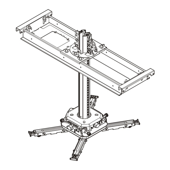
- Page 3 Installation Instructions SYSAU DIMENSIONS 415.2 16.35 129.1 5.08 88.3 503.5 3.48 19.82 294.7 MOUNT AND 11.60 COLUMN ASSEMBLED 374.3 79.7 12.7 14.74 3.14 COLUMN ADJUSTMENT INCREMENT NOTE: THIS IS A 4 SHEET DRAWING SHEET 2 - CEILING PLATE SHEET 3 - PROJECTOR MOUNT AND COLUMN SHEET 4 - UNIVERSAL INTERFACE DIMENSIONS: [MILLIMETERS] INCHES...
- Page 4 SYSAU Installation Instructions DIMENSIONS - continued ROLL MICRO/MACRO ADJUST KNOB ROLL MICRO ADJUST KNOB 3° ROLL ADJUSTMENT PITCH MICRO 10° PITCH ADJUSTMENT ADJUST KNOB 10° YAW ADJUSTMENT 176.6 6.95 PITCH MICRO/MACRO ADJUST KNOB CABLE ROUTING TIE-OFF (4) MICRO/MACRO ADJUST KNOB YAW MICRO ADJUST KNOB 45.1...
- Page 5 Installation Instructions SYSAU LEGEND Tighten Fastener Pencil Mark Apretar elemento de fijación Marcar con lápiz Befestigungsteil festziehen Stiftmarkierung Apertar fixador Marcar com lápis Serrare il fissaggio Segno a matita Bevestiging vastdraaien Potloodmerkteken Serrez les fixations Marquage au crayon Loosen Fastener Drill Hole Aflojar elemento de fijación Perforar...
- Page 6 SYSAU Installation Instructions TOOLS REQUIRED FOR INSTALLATION 5/32" (security) [included] PARTS (A) Hardware Bag 9900-002214 [Hardware bag markings match second letter of hardware] AA (4) AB (4) AC (4) AD (4) AE (4) M2.5x10mm M3x10mm M4x10mm M5x14mm M6x14mm AH (4) AI (4) AF (4) AJ (4)
- Page 7 Installation Instructions SYSAU ASSEMBLY AND INSTALLATION IMPORTANT ! : The longer screws (AF through AI) and spacers (AK) may be used if there is interference Attach Universal Interface to Projector between interface legs and any part of the projector, and if more height is required to clear elevated surfaces of the projector.
- Page 8 SYSAU Installation Instructions Place interface legs (Q) over screw adapters (AM). (See Figure 4) Example: 3 leg attachment (AN) x 3 Example: 3 leg attachment (Q) x 3 or 4 (AM) x 3 or 4 Sliding mounting screws security holes (4 per leg) Figure 4 Ensure that interface leg is firmly seated over screw adapter, and pull out end of interface leg to lock in place...
- Page 9 Installation Instructions SYSAU INSTALLING THE SUSPENDED CEILING PLATE Installing on Top of Existing Ceiling Tile only: Press center tip of ceiling tile cutter (BB) into finished side of NOTE: The SYSAU has been designed to be mounted above ceiling tile at marked location. Cut extension column hole or flush with a suspended ceiling secured by a through tile using back and forth motion.
- Page 10 SYSAU Installation Instructions Installing Support Cable 11. Loosen three wing nuts in upper side of ceiling plate assembly (R) to adjust the lateral shift of the column support. (See Figure 10) WARNING: Failure to provide adequate structural strength 12. Position column support (as required) to center support over ceiling tile hole.
- Page 11 Installation Instructions SYSAU Wood Ceiling Structure OPTIONAL (BH) x 4 additional WARNING: Anchors must be installed into wood that fasteners (BH) measures at least 3-1/2" x 1-1/2" (88.9mm x 38.1mm), and the anchor must install in the center of the narrower (1-1/2" [38.1mm]) face.
- Page 12 SYSAU Installation Instructions Move projector mount and column upward to desired position. The mount and column will lock into place as soon the column’s upward motion is stopped. CAUTION: Failure to properly tension cables (BI) may result in damage to ceiling tile framework! If necessary, pull up on the release ring found on the suspended ceiling plate assembly (R) in order to move the Thread each cable (BI) completely through cable lock (BD),...
- Page 13 Installation Instructions SYSAU Flush with Suspended Ceiling only: Re-install ceiling tile Slide projector with interface bracket into mounting slots in to fit along side(s) of SYSAU. (See Figure 19) mount base until thumb nuts are seated in the narrow portion of mounting slots against the opposite side of mounting slots.
- Page 14 SYSAU Installation Instructions Adjustments ROLL Adjustment NOTE: Be sure to use the correct adjustment feature (Yaw, Turn the ROLL adjustment locking knob (R) counterclockwise (to the left) to UNLOCK (disengage) the Roll or Pitch) when adjusting the projector mount. drive. (See Figure 23) Adjust the ROLL freely to the desired macro position, as NOTE:...
- Page 15 Installation Instructions SYSAU Cable Management Open the cable management cover on the column by opening the side with double raised edge. (See Figure 24) NOTE: The cable management cover may also be slid out of place along the column length. Place cables behind cover and close cover.
- Page 16 Europe A Franklinstraat 14, 6003 DK Weert, Netherlands P +31 (0) 495 580 852 F +31 (0) 495 580 845 Chief, a products division of Asia Pacific A Office No. 918 on 9/F, Shatin Galleria Milestone AV Technologies 18-24 Shan Mei Street...
Need help?
Do you have a question about the SYS474UW and is the answer not in the manual?
Questions and answers