Sennheiser AVX, AVX3, EKP AVX-4, EKP AVX-4-US Manual
- System manual (40 pages) ,
- Quick manual (2 pages) ,
- System manual (40 pages)
Advertisement
- 1 AVX – perfect sound you can rely on
- 2 Package contents
-
3
Product overviews
- 3.1 EKP AVX receiver
-
3.2
SKM AVX, SKM-S AVX and SK AVX transmitters
- 3.2.1 SKM AVX and SKM-S AVX handheld transmitters
- 3.2.2 BA 10 accupack for the SKM AVX or SKM-S AVX handheld transmitter
- 3.2.3 Microphone stand clamp for the handheld transmitters
- 3.2.4 SK AVX bodypack transmitter
- 3.2.5 BA 30 accupack for the SK AVX bodypack transmitter
- 3.2.6 Displays of the transmitters
- 3.3 USB power supply/charger
- 3.4 ME 2 clip-on microphone
- 3.5 MKE 2 clip-on microphone
- 4 Putting the products into operation
-
5
Using the products
- 5.1 Switching the devices on or off
- 5.2 Checking the charge status of the accupacks
- 5.3 Checking the RF signal level
- 5.4 Muting the bodypack transmitter or the SKM-S AVX handheld transmitter
- 5.5 Pairing a receiver with a transmitter
- 5.6 Identifying paired devices
- 5.7 Displaying or adjusting the receiver's audio output level
- 6 Cleaning and maintaining the products
- 7 If a problem occurs...
- 8 Specifications
- 9 Accessories
- 10 Important safety information
- 11 Documents / Resources
AVX – perfect sound you can rely on
AVX is the wireless digital microphone system for your film projects and is ideal for use with both video and DSLR cameras.
AVX features self-configuring digital transmission which eliminates time-consuming frequency setup. The ultra compact receiver can be rotated freely around its XLR connector to avoid obstructing other devices mounted on your camera. It switches on and off automatically with your camera, thereby saving battery power. AVX matches perfectly to your camera's input sensitivity without having to adjust the audio level on the microphone. From professional wedding video to documentaries, from street interviews to corporate videos, AVX just works allowing you to concentrate on creativity.
- Very fast setup
- Receiver plugs directly into the XLR audio input of the camera
- Ultra compact receiver
- Receiver switches on and off with the camera's P48 phantom power
- Optimized dynamic range
- Automatic frequency management
- AES 256 encryption
- License-free 1.9 GHz frequency range
- DSLR accessories included
- Metal housing
- Made in Germany
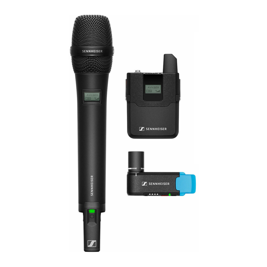
Package contents
| Package contents | Lavalier Set | Lavalier Set Pro | Handheld Set | Combo Set [1] |
| AVX-ME 2 | AVX-MKE 2 | AVX-835 | AVX-MMD 42-1 | |
| EKP AVX receiver | 1 | 1 | 1 | 1 |
| SK AVX bodypack transmitter | 1 | 1 | – | 1 |
| ME 2 clip-on microphone | 1 | – | – | 1 |
| MKE 2 clip-on microphone | – | 1 | – | – |
| SKM-S AVX handheld transmitter with mute switch incl. MMD 835-1 microphone head (cardioid) | – | – | 1 | – |
| SKM AVX handheld transmitter without mute switch incl. MMD 42-1 microphone head (omni-directional) | – | – | – | 1 |
| BA 10 accupack | – | – | 1 | 1 |
| BA 20 accupack | 1 | 1 | 1 | 1 |
| BA 30 accupack | 1 | 1 | – | 1 |
| EKP AVX adapter | 1 | 1 | 1 | 1 |
| NT 5-10U power supply unit | 1 | 1 | 1 | 1 |
| CI 400 adapter cable | 1 | 1 | 1 | 1 |
| Microphone stand clamp for handheld transmitter | – | – | 1 | 1 |
| Bag | 1 | 1 | 1 | 1 |
1 only available in the USA
Product overviews

The transmitters and the receiver are available in different country variants:
- Country variant -3 for Europe, the Mid East and Australia
- Country variant -4 for North, Central and South America (except Brazil)
- Country variant -5 for Japan
- Country variant -6 for Taiwan
- Country variant -7 for Brazil
The country variant can be found on the packaging and on the type plate  as shown on above.
- Only use the country variant permitted for use at the venue.
- Do not combine devices of different country variants.
EKP AVX receiver

- AF Out button
For displaying and adjusting the audio output level - 4-step LED display
When the On/Off/Check button has been pressed, the LED display lights up green to indicate the remaining battery life of the receiver's BA 20 accupack; when the AF Out button has been pressed, the LED display lights up red to indicate the audio output level.
When the right LED flashes red, the capacity of the receiver's BA 20 accupack is only sufficient for a maximum of 15 minutes of operation.
![]()
- BA 20 accupack
- On/Off/Check button
Short-press to switch the receiver on or to display the charge status of the accupack;
Long-press to switch the receiver off. - Status LED
lights up green:![]()
A radio link to the transmitter is established. The accupack of the received transmitter is sufficiently charged.
flashes green:
![]()
The Pair button has been short-pressed. The paired transmitter is being identified.
flashes alternately green and red:
![]()
The Pair button has been long-pressed. The receiver establishes a radio link to a transmitter whose Pair button has also been long-pressed.
lights up yellow:![]()
The received transmitter has been muted with its MUTE switch.
flashes red:
![]()
The accupack capacity of the received transmitter is only sufficient for approx. 15 minutes of operation.
lights up red:![]()
No radio link to a transmitter.


- Pair button
Short-press to identify the paired transmitter. Long-press to change the pairing. - Rotatable XLR-3 connector
For connection to the video camera or the DSLR camera
The receiver can be rotated by a maximum angle of 320°.
![]()
- EKP AVX adapter
The EKP AVX adapter consists of a hot shoe adapter and a belt clip. The belt clip allows the attachment of the receiver to a belt or a pocket.
![]()
The hot shoe adapter allows the attachment of the receiver to the hot shoe of a DSLR camera. The receiver can then be connected to the DSLR camera using the CI 400 adapter cable.


BA 20 accupack for the EKP AVX receiver

- Charge status LED
lights up green:![]()
The accupack is fully charged.
lights up red:![]()
The accupack is being charged. - Micro USB socket
for charging the accupack.


SKM AVX, SKM-S AVX and SK AVX transmitters
SKM AVX and SKM-S AVX handheld transmitters

- Unscrewable microphone head
- Display panel
- MUTE switch
for muting the SKM-S AVX handheld transmitter - ON/OFF button with status LED button
Slide briefly to switch the handheld transmitter on. Slide and hold to switch the handheld transmitter off.
lights up green:![]()
A radio link to the receiver is established. The accupack of the handheld transmitter is sufficiently charged.
flashes green:
![]()
The Pair button has been short-pressed. Paired devices are being identified.
flashes alternately green and red:
![]()
The Pair button has been long-pressed. The handheld transmitter establishes a radio link to a receiver whose Pair utton has also been long-pressed.
lights up yellow:![]()
The SKM-S AVX handheld transmitter has been muted with the MUTE switch. In addition, Muted![]() is displayed on the display panel.
is displayed on the display panel.
flashes red:
![]()
The accupack capacity of the received transmitter is only sufficient for approx. 15 minutes of operation. flashes red:
lights up red:
![]()
No radio link to a receiver. In addition, No Link![]() is displayed on the display panel.
is displayed on the display panel. - Pair button
Short-press to identify the paired receiver.
Long-press to change the pairing. - Antenna
![information]() Do not cover the antenna during transmission to avoid a reduction in the transmission range.
Do not cover the antenna during transmission to avoid a reduction in the transmission range. - BA 10 accupack


 is displayed on the display panel.

 is displayed on the display panel.
BA 10 accupack for the SKM AVX or SKM-S AVX handheld transmitter

- Charge status LED
lights up green:![]()
The accupack is fully charged.
lights up red:![]()
The accupack is being charged. - Micro USB socket
for charging the accupack - Catches
Press simultaneously to release the accupack from the handheld transmitter.


Microphone stand clamp for the handheld transmitters

- Microphone clamp
for attachment of the handheld transmitter - Thread
for screwing the microphone clamp onto a stand
SK AVX bodypack transmitter

- On/Off button
Short-press to switch the bodypack transmitter on.
Long-press to switch the bodypack transmitter off. - Mic/Line 3.5 mm jack socket
for connecting the clip-on microphone - Status LED
lights up green:![]()
A radio link to the receiver is established. The accupack of the bodypack transmitter is sufficiently charged.
flashes green:
![]()
The Pair button has been short-pressed. Paired devices are being identified.
flashes alternately green and red:
![]()
The Pair button has been long-pressed. The bodypack transmitter establishes a radio link to a receiver whose Pair button has also been long-pressed.
lights up yellow:![]()
The bodypack transmitter has been muted with its MUTE switch. In addition, Muted![]() is displayed on the display panel.
is displayed on the display panel.
flashes red:
![]()
The accupack capacity of the bodypack transmitter is only sufficient for approx. 15 minutes of operation.
lights up red:![]()
No radio link to a receiver. In addition, No Link![]() is displayed on the display panel.
is displayed on the display panel. - Antenna
![information]() Do not cover the antenna during transmission to avoid a reduction in the transmission range.
Do not cover the antenna during transmission to avoid a reduction in the transmission range. - MUTE switch
for muting the bodypack transmitter. - Display panel.
- Catches
Press simultaneously to release the accupack from the bodypack transmitter. - BA 30 accupack
- Pair button
Short-press to identify the paired receiver.
Long-press to change the pairing - Belt clip


BA 30 accupack for the SK AVX bodypack transmitter

- USB cover flap
Covers the micro USB socket for charging the accupack. - Charge status LED
lights up green:![]()
The accupack is fully charged.
lights up red:![]()
The accupack is being charged.
Displays of the transmitters

- Name of the radio link
The name of the radio link always consists of "AVX" and the last four digits of the serial number of the paired receiver. The receiver's serial number can be found on the type plate under the accupack.
You cannot change this name. - Expected battery life of the accupack
- 6-segment RF signal level display
Displays the field strength of the transmitted signal at the receiver.
USB power supply/charger
The NT 5-10U power supply/charger is suitable for recharging the BA 10 accupack (handheld transmitter), the BA 20 accupack (receiver) or the BA 30 accupack (bodypack transmitter).
 You can recharge the BA 10, BA 20 and BA 30 accupacks as follows:
- using the Sennheiser NT 5-10U USB power supply/charger
- using any USB power supply/charger
- via the USB port of a computer
- via a USB hub with its own power supply
- via a mobile USB power supply (power bank)

- NT 5-10U
USB power supply/charger (country-specific) for charging the accupacks - USB connector (type A)
for connection to the USB power supply/charger - Micro USB connector
for connection to an accupack
ME 2 clip-on microphone

- Microphone clip
for attaching the clip-on microphone to clothing - Microphone capsule
with omni-directional pick-up pattern - Anti-kink protection
to prevent cable damage - Connection cable (1.6 m)
with lockable 3.5 mm jack plug for connection to the bodypack transmitter - Foam windshield
for attenuating wind noise by 10 dB
MKE 2 clip-on microphone

- Microphone capsule
with omni-directional pick-up pattern - Anti-kink protection
to prevent cable damage - Microphone clip
for attaching the clip-on microphone to clothing - Connection cable (1.6 m)
with lockable 3.5 mm jack plug for connection to the bodypack transmitter - Frequency response caps
for sound optimization - Metal windshield
for attenuating wind noise by 20 dB - Fur windshield
for attenuating wind noise by additional 10 dB; with retaining loop for secure attachment to the clip-on microphone
Putting the products into operation

| Avoiding sources of interference | Featuring automatic interference management, the devices are capable of avoiding interfering signals at any time by automatically moving together to unused frequencies in the 1.9 GHz frequency band, without any audio interruption. However, the number of usable radio links is reduced if there are active sources of interference in the vicinity of the devices.
WiFi, Bluetooth, Sennheiser ew D1, infrared remote controls and headphones as well as UHF radio links such as Sennheiser evolution wireless G3 do not represent sources of interference. You do not have to maintain a distance to such equipment. |
| Direct line of sight | Walls and other obstacles will reduce the range. Therefore, there should always be a direct line of sight between the transmitting antenna and the receiving antenna of a radio link. |
Putting the receiver into operation
The receiver can be rotated by a maximum angle of 320° around its XLR-3 connector.

Mounting the receiver to a video camera
To mount the receiver to a video camera, proceed as follows:
- Plug the receiver's rotatable XLR connector into the camera's XLR-3 audio input.
If the video camera has an XLR-3 audio input with P48 phantom power, the receiver is automatically switched on and off together with the video camera – provided that the phantom power is automatically switched on and off together with the camera. - Rotate the receiver into position, making sure that it does not disturb during filming and that there is – preferably – a direct line of sight to the transmitter.
![]()

Mounting the receiver to a digital single-lens reflex camera
To mount the receiver to a DSLR camera, use the supplied EKP AVX adapter.
The adapter consists of a hot shoe adapter and a belt clip.
- Loosen the locking screw.
![]()
- Remove the hot shoe adapter from the belt clip.
![]()
- Slide the hot shoe adapter onto the hot shoe of the DSLR camera as shown on the left.
![]()
- Fasten the hot shoe adapter using the locking screw.
![]()
- Plug the receiver's rotatable XLR connector into the hot shoe adapter.
- Connect the XLR-3 socket of the supplied CI 400 adapter cable to the XLR3 connector of the receiver
- Connect the 3.5 mm jack plug of the CI 400 adapter cable to the 3.5 mm audio output of the DSLR camera.
![]()


Attaching the receiver using the belt clip
You can use the belt clip to attach the receiver to e.g. a belt or to the camera bag.
Proceed as follows:
- Slide the hot shoe adapter onto the belt clip.
![]()
- Fasten the hot shoe adapter to the belt clip using the locking screw.
![]()
- Plug the receiver's rotatable XLR-3 connector into the hot shoe adapter as shown on the left.
- Use the belt clip to attach the receiver to a camera bag or a belt.
![]()


Putting the bodypack transmitter into operation
Removing/inserting the accupack
You can power the bodypack transmitter with the supplied BA 30 accupack. The accupack must be charged before first time use. The accupack can remain in the bodypack transmitter for charging.
Before using the bodypack transmitter for the first time, remove the protective foil from its accupack.
To remove the accupack from the bodypack transmitter:
- Simultaneously press the two catches and pull the accupack away from the bodypack transmitter.
- Remove the protective foil.
![]()

To insert the accupack into the bodypack transmitter:
- Slide the accupack onto the bodypack transmitter as shown. The accupack locks into place with an audible click.
![]()

Attaching the bodypack transmitter to clothing
- Use the belt clip to attach the bodypack transmitter to clothing.
- The antenna of the bodypack transmitter should not be touched or covered during transmission as this would reduce the transmission range.
- There should be a free line of sight between the antenna of the bodypack transmitter and the receiving antenna.
![]()

Connecting a clip-on microphone to the bodypack transmitter
Only connect one of the clip-on microphones recommended by Sennheiser. These microphones are optimized for the bodypack transmitter.

- Connect the jack plug of the clip-on microphone to the 3.5 mm jack socket (Mic/Line) of the bodypack transmitter.
- Lock the jack plug by screwing down the coupling ring.
Putting the clip-on microphones into operation
Putting the MKE 2 into operation
The MKE 2 clip-on microphone is supplied with the Lavalier Set Pro and meets the highest demands on sound quality and ruggedness.
Using the frequency response caps
You can use the supplied frequency response caps to boost the frequency response of the MKE 2 (e.g. if the sound is too muffled) and to optimize your recordings by improving the speech intelligibility.

- Slip the frequency response cap of your choice onto the microphone capsule until it locks into place.
- The (small) MZC 2-1 frequency response cap slightly increases the treble response of the microphone.
- The (large) MZC 2-2 frequency response cap allows you to increase the treble frequencies to a greater extent.
Using the windshield
In order to avoid annoying wind noise during recording, we recommend using a suitable windshield.
The MKE 2 is supplied with a metal windshield and a fur windshield. To begin with, use the metal windshield which reduces wind noise by up to 20 dB. With the additional fur windshield, you can reduce wind noise by a further 10 dB.
The fur windshield can only be used together with the metal windshield.
![]()
To use the metal windshield:
- Slip the metal windshield onto the microphone capsule of the MKE 2. The microphone is ready for operation and can be attached to clothing by means of the supplied microphone clip.
To use the fur windshield:
- If you are already using the metal windshield or one of the frequency response caps, remove them from the microphone capsule.
- Stretch open the retaining loop of the fur windshield by moving the sleeve towards the fur. Make sure you do not accidentally remove the sleeve from the retaining loop.
- Pass the microphone through the retaining loop of the fur windshield. The retaining loop now fits loosely around the connection cable of the MKE 2.
![]()
- Slip the metal windshield onto the microphone capsule.
![]()
- Carefully stretch the opening of the fur windshield and slide it over the metal windshield. Make sure that the fur windshield completely covers the metal windshield.
![]()
- Use the sleeve to tighten the retaining loop around the connection cable. The retaining loop ensures that the fur windshield is securely attached to the clip-on microphones.
![]()


Attaching the clip-on microphone to clothing
The MKE 2 is supplied with a microphone clip that consists of two parts:

- a microphone holder
![]()
- a clip
![]() for attaching the microphone to clothing
for attaching the microphone to clothing

 for attaching the microphone to clothing
The clip has three holes. Inserting the microphone holder into one of the holes influences the clip's contact pressure and thus ensures secure attachment of the clip to clothing made of different materials:
- Hole
![]() : for attaching the microphone clip to clothing made of very heavy and tightly-woven materials
: for attaching the microphone clip to clothing made of very heavy and tightly-woven materials - Hole
![]() : for attaching the microphone clip to clothing made of medium-heavy materials
: for attaching the microphone clip to clothing made of medium-heavy materials - Hole
![]() : for attaching the microphone clip to clothing made of very thin materials
: for attaching the microphone clip to clothing made of very thin materials
 : for attaching the microphone clip to clothing made of very heavy and tightly-woven materials
 : for attaching the microphone clip to clothing made of medium-heavy materials
 : for attaching the microphone clip to clothing made of very thin materials
- Snap the connection cable of the MKE 2 into the microphone holder.
![]()
- Insert the microphone holder into the desired hole of the microphone clip.
To do so, press the two ends of the microphone holder together and hook it into the hole.
The microphone clip can be attached to clothing either vertically or horizon tally. Make sure to insert the microphone holder into the hole according to the desired orientation of the microphone clip.
![]()


To vertically attach the microphone clip to clothing:
- Guide the connection cable through the cable grip of the clip.
![]()
- Use the microphone clip to attach the clip-on microphone to clothing (e.g. lapel, collar, tie).
- Conduct the connection cable so that noise due to friction is avoided and that the connection cable and the antenna do not cross.
- Attach the microphone at a distance of approx. 25 cm to the mouth.
![]()


The MKE 2 clip-on microphone has an omni-directional pick-up pattern. It is therefore not necessary to position it precisely.
Putting the ME 2 into operation
The ME 2 clip-on microphone is supplied with the Lavalier Set and provides professional recordings with a high degree of speech intelligibility.
Using the windshield
In order to avoid annoying wind noise during recording, we recommend using a suitable windshield.
The ME 2 is supplied with a foam windshield which reduces wind noise by up to 10 dB.
To use the foam windshield:
- Slip the foam windshield onto the metal windshield of the ME 2.
![]()
Attaching the ME 2 to clothing
The ME 2 clip-on microphone is supplied with a microphone clip.
- Snap the microphone into the holder of the microphone clip.
![]()
- Use the microphone clip to attach the clip-on microphone to clothing (e.g. lapel, collar, tie).
- Conduct the connection cable so that noise due to friction is avoided and that the connection cable and the antenna do not cross.
- Attach the microphone at a distance of approx. 25 cm to the mouth.
![]()


The ME 2 clip-on microphone has an omni-directional pick-up pattern. It is therefore not necessary to position it precisely.
Putting the handheld transmitter into operation
The handheld transmitter is available both with and without Mute switch and comes with different microphone heads.
Before using the handheld transmitter for the first time, remove the protective foil from its accupack.
Removing/inserting the accupack
To remove the accupack:
- Simultaneously press the two catches and pull the accupack away from the handheld transmitter.
![]()
- Remove the protective foil.
![]()


To insert the accupack:
- Slide the accupack onto the handheld transmitter as shown. The accupack locks into place with an audible click.
![]()

Holding the handheld transmitter
If you cover the antenna of the handheld transmitter during transmission, the transmission range will be considerably reduced. If you cover the microphone head during transmission, this will change the pick-up pattern of the microphone and consequently the sound.

- Only hold the handheld transmitter by its body.
- Hold the handheld transmitter approx. 5 to 10 cm in front of your mouth.
The MMD 835-1 microphone head has a cardioid pick-up pattern:
- You can speak into the sound inlet basket from directly above or from slightly off-axis.
![]()

The MMD 42-1 microphone head has an omni-directional pick-up pattern:
- It is not necessary to orient the microphone directly towards the mouth. The microphone can also be used by several people simultaneously.
![]()

Attaching the handheld transmitter to the microphone stand clamp
- Screw the thread to the stand and tighten the screw.
- Place the handheld transmitter into the microphone clamp.
- Tilt the handheld transmitter so that it is oriented towards the mouth.
![]()

Changing the microphone head
The handheld transmitter comes in different sets, including either the MMD 835-1 or the MMD 42-1 microphone head. You can unscrew the microphone head and replace it by another one, e.g. one with a different pick-up pattern.

Recharging the accupack
You can recharge the supplied BA 10, BA 20 and BA 30 accupacks as follows:
- using the Sennheiser NT 5-10U USB power supply/charger
- using a standard USB power supply/charger
- via the USB port of a computer
- via a USB hub with its own power supply
- via a mobile USB power supply (power bank)
![]()

Charging the accupacks using the NT 5-10U power supply/charger
The BA 20 accupack of the receiver and the BA 30 accupack of the bodypack transmitter can remain in their respective devices for charging. To charge the BA 10 accupack of the handheld transmitter:
- Remove the accupack from the handheld transmitter.
- If the accupack's micro USB socket has a cover flap:
Open the cover flap of the micro USB socket of the accupack and connect the micro USB connector of the USB cable to the micro USB socket of the accupack.
To charge the accupack via the USB port of a computer or a mobile USB power supply (power bank):
- Connect the USB connector of the USB cable to a USB socket of the computer or the mobile USB power supply.
- Switch the computer or the mobile USB power supply on.
Putting the products into operation
To charge the accupack using any USB power supply/charger or a USB hub with external power supply:
- Connect the USB connector of the USB cable to the USB socket of the USB power supply/charger or to the USB hub.
- Plug the USB power supply/charger or the power supply unit of the USB hub into the wall socket.
The charge status LED of the accupack lights up red when the accupack is being charged. The charge status LED of the accupack lights up green when the accupack is fully charged.
| Accupack | Charging time required for a capacity of... | |||
| ... 30 % | ... 60 % | ... 75 % | ... 100 % | |
| BA 10 (handheld transmitter) | 1:00 h | 2:00 h | 3:00 h | 4:30 h |
| BA 20 (receiver) | 0:15 h | 0:30 h | 0:40 h | 1:15 h |
| BA 30 (bodypack transmitter) | 1:00 h | 2:00 h | 3:00 h | 4:30 h |
Using the products
AVX offers true ease of use:
- The devices of a set are factory pre-paired and ready for immediate use.
- The system features automatic frequency management and automatically searches for free transmission frequencies.
- AVX also features automatic interference management and inaudibly shifts to a new frequency if interference occurs.
- The system also sets the correct microphone sensitivity automatically.
- Sound that is too loud or, even worse, too quiet is now a thing of the past.
Switching the devices on or off
After switch-on, the receiver and the transmitter will take approx. 10 seconds to establish the radio link. The more sources of interference there are and the more AVX devices you switch on, the longer it takes to establish the radio links.
Switching the receiver on
If the receiver is connected to an XLR-3 audio input with P48 phantom power, the receiver is automatically switched on together with the video camera – provided that the phantom power is automatically switched on together with the camera.
To manually switch the receiver on:
- Short-press the On/Off/Check button.
The status LED indicates the current status of the receiver. The radio link to the last paired transmitter is established automatically as soon as the paired transmitter is switched on.
![]()

Switching the receiver off
If the receiver is connected to an XLR-3 audio input with P48 phantom power, the receiver is automatically switched off together with the video camera – provided that the phantom power is automatically switched off together with the camera. If, after switch-off of the video camera, the phantom power drops only slowly, the receiver can take up to one minute to switch off.
To manually switch the receiver off:
- Long-press the On/Off/Check button.
The status LED goes off.
![]()

Switching the bodypack transmitter on
- Short-press the On/Off button.
The display panel and the status LED indicate the current status of the bodypack transmitter. The radio link to the last paired receiver is automatically established as soon as the paired receiver is switched on.
![]()

Switching the bodypack transmitter off
- Long-press the On/Off button.
The display panel and the status LED go off.
![]()

Switching the handheld transmitter on
- Briefly slide the On/Off button in the direction of the transmitter body.
![]()
The display panel and the status LED indicate the current status of the handheld transmitter. The radio link to the last paired receiver is automatically established as soon as the paired receiver is switched on.
![]()


Switching the handheld transmitter off
- Slide and hold the On/Off button in the direction of the transmitter body.
![]()
The display panel and the status LED go off.
![]()


Checking the charge status of the accupacks
Checking the charge status of the BA 20 accupack in the receiver
To display the expected remaining battery life of the BA 20 accupack in the receiver:
- Short-press the On/Off/Check button.
The 4-step LED display lights up green to indicate the expected remaining battery life.

When the right LED of the 4-step LED display flashes red – regardless of whether the On/Off/Check button has been pressed –, the capacity of the BA 20 accupack is only sufficient for less than 15 minutes of operation.
![]()


Checking the charge status of the BA 10 accupack in the handheld transmitter or of the BA 30 accupack in the bodypack transmitter
The expected remaining battery life of the accupack is indicated by a battery icon on the transmitter display panel.

When the capacity of the accupack is so low that the remaining battery life is less than 30 minutes, the status LED on both the transmitter and the receiver flashes red.

In addition, the empty battery icon flashes on the display panel of the transmitter.

Checking the RF signal level
The quality of the RF signal is shown on the display panel of the transmitter

If no RF signal is being transmitted, e.g. because the receiver is switched off or out of range, all segments of the RF signal level display are grayed out. In addition, No Link  is displayed on the display panel.
Muting the bodypack transmitter or the SKM-S AVX handheld transmitter
Both the bodypack transmitter and the SKM-S AVX handheld transmitter have a Mute switch that mutes the audio signal without switching the transmitter off.

The SKM AVX handheld transmitter has no Mute switch and can therefore not be muted.
- Slide the Mute switch to the position Mute. Muted
![]() appears on the display panel of the transmitter. The status LED on both the transmitter and the paired receiver lights up yellow
appears on the display panel of the transmitter. The status LED on both the transmitter and the paired receiver lights up yellow ![]() .
. - Slide the Mute switch to the position Mic to unmute the audio signal.
 .
.Pairing a receiver with a transmitter
The receiver and the transmitter of a set are factory pre-paired and therefore ready for immediate use. The radio link is automatically established as soon as both devices are switched on. You can disconnect the existing radio link and establish new radio links to two other devices.
To establish a new radio link between a receiver and a transmitter, proceed as follows:
- Switch on the receiver and the transmitter that you want to pair.
The status LED on both the receiver and the transmitter indicates the current device status. - Long-press, one after the other, the Pair buttons of the receiver and the transmitter to be paired until their status LEDs flash alternately green and red. You have 120 seconds between pressing the first button and the second button.
![]()
Press pair on receiver appears on the transmitter display panel. Existing radio links to other devices are now disconnected. - Wait for approx. 10 seconds until the radio link is established.
![]() - Once the radio link is successfully established, Paired
- Once the radio link is successfully established, Paired ![]() appears on the transmitter display panel and the status LED on both the transmitter and the receiver lights up green.
appears on the transmitter display panel and the status LED on both the transmitter and the receiver lights up green.
![]() - If no radio link can be established, Pairing failed
- If no radio link can be established, Pairing failed ![]() briefly appears on the transmitter display panel, followed by the message No Link
briefly appears on the transmitter display panel, followed by the message No Link ![]() . The status LED of the transmitter and/or the receiver lights up red.
. The status LED of the transmitter and/or the receiver lights up red.

For more information on potential problems when establishing a radio link.
Identifying paired devices
You can perform a pairing identification to see which transmitter is paired with which receiver.
- Switch on all devices whose pairing you want to identify.
- Short-press the Pair button of the receiver or of the transmitter. The transmitter display panel displays the message This is AVX and the last four digits of the serial number of the paired receiver. The status LEDs of the paired devices flash green for 10 seconds.
If the receiver or the transmitter is not paired or if the paired device is not switched on or out of range, the status LED does not flash green.
![]()

Displaying or adjusting the receiver's audio output level
To display and correctly adjust the receiver's output level:
- Make sure that the radio link is established.
- If your video or DSLR camera has an automatic level control, the automatic level control must be deactivated.
The receiver also has an automatic level control which cannot be deactivated. If both the automatic level control of the video camera and the automatic level control of the receiver are active, they will interfere with one another.
![]()
- Short-press the AF Out button on the receiver.
The 4-step LED display indicates the current output level. This display automatically goes off after a while.
![]()
- Check the output level display on the video or DSLR camera while using the microphone as usual.
The output level is adjusted correctly when the output level display shows full deflection only during the loudest passages. If your video or DSLR camera has a clipping display, this must never light up.
![]()


If the output level is adjusted to low or too high:
- Short-press the AF Out button on the receiver while the 4-step LED display is active.
The audio output level is reduced by one step each time the AF Out button is pressed. When the lowest output level has been reached, you can press the AF Out button again to reset the receiver to the highest output level. - Alternatively, you can also adjust the input sensitivity of the video camera.
Cleaning and maintaining the products
Important safety information
 ATTENTION
Liquids can damage the electronics of the devices
Liquids entering the housing of the devices can cause a short-circuit and damage the electronics.
- Only clean the devices with a soft, dry cloth.
ATTENTION
Damage to the surfaces of the devices
Solvents or cleansing agents can damage the surfaces of the devices.
- Do not use any solvents or cleansing agents.
- Use devices that are frequently worn on the body so that direct skin contact and contact with sweat is avoided.
- Use a dry cloth to clean all devices that are frequently worn on the body from time to time.
Cleaning the sound inlet basket of the handheld transmitter
- Unscrew the sound inlet basket from the handheld transmitter.
![]()
- Unscrew the upper part of the sound inlet basket from the lower part.
![]()
- Remove the foam insert from the upper part of the sound inlet basket.
![]()
- Use a dry cloth to clean the upper part of the sound inlet basket from the inside and outside.
- Reinsert the foam insert into the upper part of the sound inlet basket.
- Screw the upper part of the sound inlet basket back to the lower part.
- Replace the sound inlet basket on the handheld transmitter and screw it tight.


If a problem occurs...
| Problem | Possible cause | Possible solution |
| No sound | The receiver is not connected properly. |
|
The bodypack transmitter or the SKM-S AVX handheld transmitter is muted. Muted  appears on the transmitter display panel and the status LED on both the receiver and the transmitter lights up yellow. appears on the transmitter display panel and the status LED on both the receiver and the transmitter lights up yellow. |
| |
| The transmitter and the receiver are not paired, the status LED lights up red. |
| |
| Sound distorted | The automatic level control of the video camera or the DSLR camera is active. | Deactivate the automatic level control of the video camera or the DSLR camera. |
| Sound too low | The output level of the receiver and/or the input sensitivity of the video camera is adjusted too low. |
|
| Bad reception | The distance between the transmitter and the receiver is too high. |
|
| Devices take a very long time to establish a radio link | The devices need more time to establish the radio links because the distance between the transmitter and the receiver is too large or because there are many active interfering sources in the vicinity of the devices. |
|
| Devices cannot be paired | No radio link |
|
| Different country variants | Transmitters and receivers of different country variants cannot be paired with each other. |
For more tips and answers to your questions, visit www.sennheiser.com/AVX-support
If a problem occurs that is not listed in the above table or if the problem cannot be solved with the proposed solutions, please contact your local Sennheiser partner for assistance. To find a Sennheiser partner in your country, search at www.sennheiser.com under "Service & Support".
Specifications
System
| AF frequency response | 20 to 20,000 Hz |
| Dynamic range | > 120 dB (A) |
| THD (1 kHz) | typ. 0,1 % |
| Audio sampling | 24 bit/48 kHz |
| Signal-to-noise ratio | > 90 dB (A) |
| RF frequency ranges | 1,880 to 1,930 MHz (country-specific) |
| Europe Indonesia Hong Kong Singapore Malaysia Vietnam Australia N ew Zealand | 1880 - 1900 MHz |
| Taiwan | 1880 - 1895 MHz |
| Japan | 1893 - 1906 MHz |
| Brazil | 1910 - 1920 MHz |
| USA Canada Argentina Mexico | 1920 - 1930 MHz |
| Modulation | GFSK with back channel |
| Transmission method | TDMA fast switching antenna diversity |
| Latency | 19 ms |
| Relative air humidity | max. 95 % |
| Temperature range: | |
| Operation: Storage | – 10°C to +55°C – 20°C to +70°C |
EKP AVX

| RF sensitivity | < –90 dBm |
| RF output power of back channel | typ. 15 dBm e.i.r.p. |
| Audio output XLR, balanced | adjustable –30 dBu to 0 dBu in 4 steps |
| Power supply | BA 20 accupack (Li-Ion, 3.7 V DC) |
| Operating time | > 4 h |
| AF connection socket | XLR, male |
| Weight (incl. accupack) | approx. 87 g |
AF connector | 3.5 mm jack plug, unbalanced Connector assignment: |
| AF connection socket | XLR, female Pin assignment: |
SKM AVX

| RF output power | adaptive, up to 250 mW (country-specific) |
| AF frequency response | 50 to 20,000 Hz |
| Input sensitivity | automatic sensitivity adjustment |
| Power supply | BA 10 accupack (Li-Ion, 3.6 V DC) |
| Operating time with accupack | typ. 15 h |
| Display | LCD |
| Weight (without accupack) | approx. 282 g incl. microphone head |
SK AVX

| RF output power | adaptive, up to 250 mW (country-specific) |
| AF frequency response | |
| Mic: Line: | 50 to 20,000 Hz 20 to 20,000 Hz |
| Max. input level | |
| Mic: Line: | 2.2 V RMS 3.3 V RMS |
| Line input impedance | 1 MΩ |
| Input sensitivity | automatic sensitivity adjustment |
| Power supply | BA 30 accupack (Li-Ion, 3.7 V DC) |
| Operating time with accupack | typ. 15 h |
| AF connection socket | 3 5 mm jack socket, lockable Connector assignment:  |
| Weight (without accupack) | approx. 87 g |
Microphones

MMD 835-1
| Microphone type | dynamic |
| Sensitivity | 2.1 mV/Pa |
| Pick-up pattern | cardioid |
| Max. SPL | 154 dB SPL |
MMD 42-1
| Microphone type | dynamic |
| Sensitivity | 1.8 mV/Pa |
| Pick-up pattern | omni-directional |
| Max. SPL | 154 dB SPL |
ME 2

| Microphone type | pre-polarized condenser microphone |
| Sensitivity | 20 mV/Pa |
| Pick-up pattern | omni-directional |
| Max. SPL | 130 dB SPL |
MKE 2

| Microphone type | pre-polarized condenser microphone |
| Sensitivity | 5 mV/Pa |
| Pick-up pattern | omni-directional |
| Max. SPL | 142 dB SPL |
In compliance with:
| Europe | Radio - EN 301406 Safety - RoHS - EN 50581 |
| USA | FCC 47 CFR 15 |
| Canada | Industry Canada RSS 210 CAN ICES-3(B)/NMB-3(B) |
Approved by:
| USA | |
| SKM SK EKP | FCC ID: DMOSKM1G49WE FCC ID: DMOSK1G9WE FCC ID: DMOEKP1G9WE |
| Canada | |
| SKM SK EKP | IC: 2099A-SKM1G9WE IC: 2099A-SK1G9WE IC: 2099A-EKP1G9WE |
Australia/New Zealand Japan

Japan

USB power supply/charger

NT 5-10U
| Nominal input voltage | 100 to 240 V~ |
| Power frequency | 50 or 60 Hz |
| Nominal output voltage | 5 V  |
| Output current | 1 A |
| Standby power consumption | ≤ 0.1 W |
| Energy efficiency level | V |
| Operating temperature | 0°C to +40°C |
| Storage temperature | –20°C to +70°C |
| Relative air humidity | max. 90 % |
| Weight | approx. 55 g |
Accupacks
BA 10 | Charging capacity Output voltage | 2,200 mAh 3.6 V |
BA 20 | Charging capacity Output voltage | 430 mAh 3.7 V |
BA 30 | Charging capacity Output voltage | 2,030 mAh 3.7 V |
Dimensions
Receiver

Handheld transmitter

Bodypack transmitter

Accessories
Receiver
- EKP AVX receiver incl. NT 5-10U power supply unit
Antenna and connection cables
- CI 400 adapter cable
Transmitters
- SK AVX bodypack transmitter incl. BA 30 accupack
- SKM AVX handheld transmitter without mute switch without microphone head incl. BA 10 accupack
- SKM-S AVX handheld transmitter with mute switch without microphone head incl. BA 10 accupack
Microphones for the bodypack transmitter
- ME 2 clip-on microphone incl. accessories
- MKE 2 clip-on microphone incl. accessories
Microphone heads for the handheld transmitter
- MMD 42-1, dynamic, omni-directional
- MMD 835, dynamic, cardioid
Windshields
- MZW 1 windshield for the handheld transmitter
Power supply units
- NT 5-10U USB power supply/charger
Accupacks
- BA 10 accupack for the handheld transmitter
- BA 20 accupack for the receiver
- BA 30 accupack for the bodypack transmitter
Protective case
- Bag for the handheld or bodypack transmitter
Important safety information
- Read these safety instructions and the instruction manuals of the products.
- Keep these safety instructions and the instruction manuals of the products. Always include these safety instructions and the instruction manuals when passing the products on to third parties.
- Heed all warnings.
- Follow all instructions.
- Do not use the products near water.
- Do not operate near any heat sources such as radiators, stoves, or other apparatus (including amplifiers) that produce heat.
- Only operate the products from the types of power source specified in the chapter "Specifications" and indicated on the power supply unit.
- Unplug the power supply units from the wall socket,
- to completely disconnect the products from the power supply system,
- during lightning storms or
- when not using the products for long periods of time.
- Always ensure that the power supply units are
- in a safe operating condition and easily accessible,
- properly plugged into the wall socket,
- only operated within the permissible temperature range,
- not covered or exposed to direct sunlight for longer periods of time in order to prevent heat accumulation.
- Protect the power cords from being walked on or pinched, particularly at the points where they exit from wall sockets, power supply units and products.
- Only use attachments, accessories or spare parts specified by Sennheiser
- Refer all servicing to qualified service personnel. Servicing is required when the products have been damaged in any way, liquid has been spilled or objects have fallen into the products, when the products has been exposed to rain or moisture, do not operate normally, or have been dropped.
![]()
![]()
To reduce the risk of fire or electric shock, do not expose the products to rain or moisture.- Do not expose the products to dripping or splashing. Ensure that no objects filled with liquids, such as vases, are placed on the products.


Safety instructions for lithium-ion rechargeable batteries
If abused or misused, the rechargeable batteries may leak. In extreme cases, they may even present a risk of
- explosion,
- fire development,
- heat generation,
- smoke or gas development.
Sennheiser does not accept any liability for damage arising from abuse or misuse.
- Keep away from children.
- Only charge rechargeable batteries with chargers recommended by Sennheiser.
- Observe correct polarity.
- Pack/store charged rechargeable batteries so that the terminals cannot contact each other – danger of shorting out/fire hazard.
- Do not expose to moisture.
- Switch rechargeable battery-powered products off after use.
- Only charge rechargeable batteries at ambient temperatures between 10°C/50°F and 40°C/104°F.
- When not using rechargeable batteries for extended periods of time, charge them regularly (about every three months).
- Do not mutilate or dismantle.
- Do not heat above 60°C/140°F, e.g. do not expose to sunlight or throw into a fire.
- Immediately remove rechargeable batteries from obviously defective products.
- Do not continue to use defective rechargeable batteries.
- Only use rechargeable batteries specified by Sennheiser.
- Dispose of rechargeable batteries at special collection points or return them to your specialist dealer.
- Store the products in a cool and dry place at room temperature (approx. 20°C/68°F).
- Remove the rechargeable batteries if the products will not be used for extended periods of time.
Intended use
The microphones, the transmitters, the receiver and the accessories of the Sennheiser AVX system can be combined with each other and have been designed for use in video recordings in dry environments.
In order that speech, music and vocals are transmitted in the best possible quality, the receiver has to be connected, as described in this instruction manual, to a video camera or a DSLR camera with video recording function.
The products can be used for commercial purposes.
Intended use includes:
- having read and understood these safety instructions and the instruction manuals of the products
- using the products within the operating conditions and limitations described in these safety instructions and in the instruction manuals of the products.
It is considered improper use when the products are used for any application not named in the instruction manuals of the products.
Sennheiser does not accept liability for damage arising from abuse or misuse of the products and their accessories.
Documents / Resources
References
Download manual
Here you can download full pdf version of manual, it may contain additional safety instructions, warranty information, FCC rules, etc.
Download Sennheiser AVX, AVX3, EKP AVX-4, EKP AVX-4-US Manual
Advertisement


Need help?
Do you have a question about the AVX and is the answer not in the manual?
Questions and answers