Advertisement
Quick Links
INSTALLATION MANUAL
AIR CONDITIONER (SPLIT TYPE)
Scan QR CODE to access installation and owner's manual on website.
https://www.toshiba-carrier.co.th/manuals/default.aspx
Manual are available in EN/SV/FI/NO/DA/LV/LT/ET.
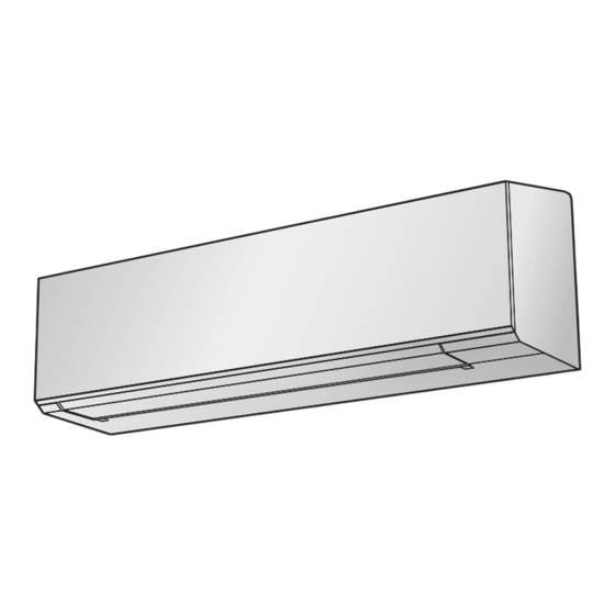
Indoor unit
RAS-B50G3KVSG-ND
Outdoor unit
RAS-50G3AVSG-ND
R32
ENGLISH
114 435 01 08- 1A
Advertisement

Summary of Contents for Toshiba RAS-B50G3KVSG-ND
- Page 1 INSTALLATION MANUAL ENGLISH AIR CONDITIONER (SPLIT TYPE) Scan QR CODE to access installation and owner’s manual on website. https://www.toshiba-carrier.co.th/manuals/default.aspx Manual are available in EN/SV/FI/NO/DA/LV/LT/ET. Indoor unit RAS-B50G3KVSG-ND Outdoor unit RAS-50G3AVSG-ND 114 435 01 08- 1A...
- Page 2 CONTENTS ACCESSORY PARTS .................................1 INSTALLATION DIAGRAM OF INDOOR AND OUTDOOR UNITS ...................2 Optional Installation Parts ..............................2 INDOOR UNIT ..................................3 Installation Place................................3 Cutting a Hole and Mounting Installation Plate ........................3 How to Connect Remote Controller for Wire Operation....................4 Piping and Drain Hose Installation ..........................5 Indoor Unit Fixing................................6 Drainage ..................................6 OUTDOOR UNIT .................................6...
- Page 3 ACCESSORY PARTS ACCESSORY PARTS Indoor Unit Part name Part name Installation plate × 1 Wireless remote controller × 1 Battery × 2 Remote controller holder × 1 Mounting screw × 6 Flat head wood screw × 2 Flat head wood screw × 1 Battery cover Owner’s Manual ×...
- Page 4 INSTALLATION DIAGRAM OF INDOOR AND OUTDOOR UNITS INSTALLATION DIAGRAM OF INDOOR AND OUTDOOR UNITS For the rear left, bottom left and left piping Wall Hook Installation plate Cut out a piece of SPACER from indoor unit packaging box, roll it and insert Flat head between the indoor unit and wall to tilt wood screw...
- Page 5 INDOOR UNIT INDOOR UNIT • Space allows for moving range of the air inlet grille and horizontal louver Installation Place in operation above curtain rails, window cornice or other objects. • A place which provides the spaces around the indoor unit as shown in the (Unit : mm) diagram.
- Page 6 6. Set control wire through gutter way at rear side of remote controller as How to Connect Remote Controller shown on fi gure 8. 7. Fix provided screw (Ø3.1×16L) on the wall to hang remote controller as for Wire Operation shown on fi...
- Page 7 In case of bottom right or bottom left piping Piping and Drain Hose Installation • After scribing slits of the front panel with a knife or a making-off pin, cut Piping and drain hose forming them with a pair of nippers or an equivalent tool.
- Page 8 Drainage Indoor Unit Fixing 1. Pass the pipe through the hole in the wall and hook the indoor unit on the 1. Run the drain hose sloped downwards. installation plate at the upper hook. NOTE 2. Swing the indoor unit to right and left to confi rm that it is fi rmly hooked up on the installation plate.
- Page 9 • As shown in the fi gure below, install the foundation and vibration-proof CAUTION rubber pads to directly support the bottom surface of the fi xing leg that is in contact with and underneath the bottom plate of the outdoor unit. 1.
- Page 10 Draining the Water Refrigerant Piping • Holes are provided on the base plate of the outdoor unit to ensure that the Knockout of pipe cover defrost water produced during heating operations is drained off effi ciently. If a centralized drain is required when installing the unit on a balcony or Knockout procedure wall, follow the steps below to drain off the water.
- Page 11 Refrigerant Piping Connection CAUTION 1. Do not put the crescent wrench on the cap or cover. Flaring The valve may break. 2. If applying excessive torque, the nut may break according to some installation conditions. 1. Cut the pipe with a pipe cutter. Obliquity Roughness Warp...
- Page 12 Packed valve handling precautions Evacuating • Open the valve stem all the way out, but do not try to open it beyond the After the piping has been connected to the indoor unit, you can perform stopper. vacuuming together at once. Pipe size of Packed Valve Size of Hexagon wrench Vacuuming...
- Page 13 The power supply can be selected to connect to indoor unit or outdoor unit. Choose proper way and connect the power supply and connecting cable by follow the instruction as following. Model RAS-B50G3KVSG-ND Power source 50 Hz, 220 – 240 V Single phase Maximum running current 15.85 A...
- Page 14 In Case of Indoor Unit Connect With 1:1 Outdoor Unit Power Supply Input at Outdoor Unit Terminal Block (Recommend) Indoor Unit Outdoor Unit Connecting cable Stripping length of the Connecting cable 1 2 3 connect to 1 2 3 connecting cable Terminal block Earth line 50 mm...
- Page 15 Power supply input Wiring Diagram for 1:1 Outdoor Unit Power supply input at Outdoor Terminal Block (Recommend) Indoor L N 1 2 3 Terminal Block Outdoor 1 2 3 Terminal Block L N GND Power supply input Power supply input at Indoor Terminal Block (Optional) Indoor Terminal Block...
- Page 16 In Case of Indoor Unit Connect With Inverter Multi System (IMS) Power Supply Input at Outdoor Unit Terminal Block Indoor Unit Outdoor Unit Connecting cable Stripping length of the Connecting cable 1(L) connect to 1 2 3 connecting cable Terminal block Earth line 50 mm 10 mm...
- Page 17 OTHERS OTHERS Gas Leak Test Test Operation Indoor unit inspection locations To switch the TEST RUN (COOL) mode, press [RESET] button for (piping connections) 10 seconds. (The beeper will make a short beep.) Refrigerant piping Indoor unit side piping OPERATION / RESET Button Auto Restart Function Setting Outdoor unit inspection locations...
- Page 19 INSTALLATION CHECK LIST INSTALLATION CHECK LIST Model name After finishing installation work, please check items below and hand this sheet to user to keep it in a safe place together with Owner and Installation Manuals Check date Checked by Note : Please put a mark " "...


Need help?
Do you have a question about the RAS-B50G3KVSG-ND and is the answer not in the manual?
Questions and answers