Advertisement
Quick Links
1
For safe operations
This product is not explosion-proof. Be sure to take extreme care for safety during
operation.
Warning
This product has not been designed as explosion proof.
Operating in a dangerous atmosphere may cause a fire.
Caution
Wrong connection of pipes may prevent normal operation of the unit
and may cause a malfunction or an accident.
2 Product overview
2-1 Application
WARNING
Never attempt to modify the product.
Operate the unit for the specified purpose
only.
An electric shock or a malfunction may result if
the product is modified or used for any
purposes other than that specified.
This vacuum pump is a depressurizing unit for a
condensation unit including a rotary evaporator,
a test tube evaporator or a centrifugal evaporator,
a vacuum drying unit or a suction filter.
Never install the unit in a dangerous atmosphere.
Connect pipes as instructed.
※This product employs anti-corrosion parts,
which does not necessarily mean it withstands all
types of solvents.
Depending on the solvent or the operating
conditions, the diaphragm, the valves or the
suction/discharge nozzles might degrade and lead
to compromised depressurizing capacity.
When this is suspected, install a solvent collector
such as a cooling trap between the depressurizing
container and the vacuum pump and operate for
about five minutes without any load to suction air
for cleaning.
Replacement of the diaphragm and the valves
require adjustment. Ask your dealer or nearest
service center for such work.
-1-
Advertisement

Related Manuals for EYELA NVP-1000V

Summary of Contents for EYELA NVP-1000V
- Page 1 For safe operations This product is not explosion-proof. Be sure to take extreme care for safety during operation. Never install the unit in a dangerous atmosphere. Warning This product has not been designed as explosion proof. Operating in a dangerous atmosphere may cause a fire. Connect pipes as instructed.
-
Page 2: Specifications
2-2 Specifications Product name Inverter diaphragm type vacuum pump Model NVP-1000V NVP-2000V NVP-2100V Discharge rate 30L/min・20L/min 44L/min・30L/min 30L/min・20L/min (HIGH・LOW) Attainable vacuum level 10hPa(Approx. 7.5Torr) 2hPa(Approx. 1.5Torr) Safety function Motor malfunction detection Motor Output 90W Cylinder 2 stages 4 stages 2 stages×2 Gas contacting part Teflon ®, PPS, Kalrez®... -
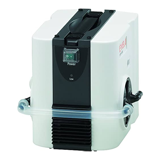
Page 3: Names Of Parts
2-3 Names of parts ■Model NVP-1000V Handle Power switch Silencer LOW /NVC lamp Discharge nozzle Pipe coupler (O.D. 10mm) Suction nozzle (L) (O.D. 10mm) Gas ballast valve NVC connector Suction nozzle Silencer (O.D. 10mm) Power selector switch Inlet with a fuse... - Page 4 ■Model NVP-2000V Handle Power switch Silencer Discharge nozzle (O.D. 10mm) LOW/NVC lamp Suction nozzle (O.D. 10mm) T-pipe coupler Pipe coupler Gas ballast valve T-pipe coupler NVC connector Suction nozzle (O.D. 10mm Silencer Power selector switch Inlet with a fuse...
- Page 5 ■Model NVP-2100V Handle Suction nozzle (O.D. 10mm) Power switch Silencer LOW /NVC Discharge lamp nozzle (O.D. 10mm) Gas ballast valve Pipe coupler Pipe coupler Suction nozzle (O.D. 10mm) NVC connector Power selector Silencer switch Inlet with a fuse...
-
Page 6: Safety Functions
3 Names and functions of the controller 3-1 NVC connector ・ power selector switch ③ Power switch ①NVC connector ② Power selector switch ④LOW/NVC lamp Name Description ① NVC connector Connect a dedicated cord to this connector when it is to be used in combination with the vacuum controller (model NVC-3000). -
Page 7: Installation Environment
4 Installation 4-1 Installation environment Caution Warning Do not install the product in a Install the product on a level , potentially hazardous location. stable and firm surface. This products is not designed with explosion- Installation and operation on a slope, proof structure. - Page 8 Required power supply connected. Product type Voltage / Capacity Power supply to be connected to the product is as shown in the right. NVP-1000V AC115V / 15A NVP-2000V AC220V / 7A (2) Check the AC outlet at the installation NVP-2100V location.
-
Page 9: Preparing For Operation
5 Operation 5-1 Preparing for operation Caution Warning Assure proper ventilation when Never attempt to operate the pump suctioning organic solvent with the sealing stopper (white resin cap) attached on the discharge Operating the unit in an organic solvent nozzle. atmosphere may cause an abnormal odor or damage to health. - Page 10 Discharge Thin nozzle the discharge nozzle. nozzle Thick nozzle Installing the silencer (NVP-1000V,2100V) Connect with the ※Connect with the flat surface of the silencer flat surface of the Silencer facing the NVP main unit so that the silencer silencer facing the will not interfere with the NVP main unit.
- Page 11 ※ Take care not to mistake the suction nozzle for No boss on the top the discharge nozzle. Check the direction of the of the discharge arrow on the exterior case. The discharge nozzle pressure of the discharge side is 0.2MPa or Direction of the higher.
- Page 12 5ー2 Operating procedures Caution Caution Stop operating the unit if you To end operation, be sure to release notice an abnormality. depressurization before turning the power switch OFF. When you notice an abnormality, immediately turn the power switch off and take appropriate Turning the power switch OFF without releasing measures referring to the section “Causes depressurization might have adverse effects on...
- Page 13 (3)Secure NVP-3000 by using face screws NVC-3000 attached to the mounting plate (Model, NVC3000-NVP-V) Mounting plate NVC3000-NVP-V Face screws (4)Using the cord to connect NVC-NVPV (Model Connect the NVC-NVPV NNV0.5M), connect NVC-3000 and NVP. connecting cord Connect NVC-3000 to the “Inverter Pump” NNV0.5M to the connector on the backside and NVP to the NVC NVC-3000...
- Page 14 5-2-2 For independent use of NVP (1) Turn the power switch ON. The motor rotates, starts suctioning at the suction nozzle, discharging at the discharge nozzle to start depressurization. ※ Amount of discharged air is larger at start resulting in a louder discharge noise. ※...
-
Page 15: Troubleshooting And Countermeasures
Contact your dealer or the nearest Troubleshooting and countermeasures service center for troubles not listed here. Symptom Cause Countermeasures Power is not supplied. Turn on the circuit breaker of the switchboard. Power cannot be turned The power plug is disconnected from Turn off the power switch, and firmly insert the electric outlet or inserted the power plug to the electric outlet. -
Page 16: Maintenance And Inspection
7 Maintenance and Inspection 7-1 Cleaning and care of the product Caution Caution Always employ and use correct Never attempt to disassembly the procedures and items for cleaning product. and maintenance. Never splash water over the external package or The unit contains parts with high voltage the inside or use scorching powder, thinner, applied or may become hot, and disassembly petroleum, kerosene, acid or similar items. -
Page 17: Replacing A Fuse
7-2 Replacing a fuse Caution Be sure to use a specified type of fuse. Fuses not specified may not blow when overcurrent flows and may lead to a fire. Two fuses are used (1) Turn the power switch OFF and remove the power cord from the fused inlet. - Page 18 Pipe coupler T-pipe coupler for for NVP(S) coupler for NVP(L) Code No. 263960 263970 263980 No. for NVP-1000 No. for NVP-2000 Pipe coupler No. for NVP-2100 NVP-1000V Pipe coupler T-pipe coupler T-pipe coupler NVP-2000V Pipe coupler Pipe coupler NVP-2100V -18-...
- Page 19 (1) Pull out the pipe coupler. Hold the both ends of the pipe coupler and pull it out. Hold the both ends of the pipe coupler and pull it out. (2) Install a pipe coupler of the same type as the original.
-
Page 20: Cleaning The Nozzle
7-4 Cleaning the nozzle When the nozzle become dirty and the performance has become low, remove and clean it with the following procedures. Loosen the screws and remove the nozzle holding plate and the Loosen two screws of the nozzle holding plate and suction (discharge) nozzle. - Page 21 7-5 Replacing the L・I-nozzle Follow the procedures below to replace the L・I-nozzle. Suction Discharge nozzle has a nozzle has boss on top. not boss on top. Code No. Name Code No. Name Code No. Name L-nozzle set L-nozzle set I-nozzle set for 263920 for NVP 263940...
- Page 22 Attach the O-ring onto the nozzle periphery with care not to scratch and twist. And install the valve with the O-ring to the pump head. When installing, ensure that no dust is adhering onto the pump head or the valve. The direction of the valve is different between Exhaust and Suction.
-
Page 23: Disposal Of The Product
When disposing the product, please follow the instructions as below. Main components and disposal instructions External dimensions (mm) Component Model Weight Method for disposing ( including protrusions) Approx. NVP-1000V 138(177)W×206(260)D×180H Inverter diaphragm Approx. Request the disposal NVP-2000V 138(177)W×206(260)D×252H vacuum operator for disposal. -
Page 24: After-Sale Services
After-sale Services 1. In case product does function 3. Repair during the guarantee period will be satisfactorily, check first by referring to the page made according to the guarantee stipulations. on troubleshooting to see if this is actually a trouble. 4. - Page 25 List of consumables and replacement parts/ optional parts 10-1 Consumables and replacement parts ①Silencer for NVP ②L-shaped nozzle set for NVP (suction) Spec. Q’ty Code No. Spec. Q’ty Code No. 263910 1set 263920 ④I-shaped nozzle set for NVP ③L-shaped nozzle set for NVP (discharge) Spec.
- Page 26 ⑨Power cord A Type ⑩Power cord B Type for 115V Spec. for 220V Spec. Spec. Q’ty Code No. Spec. Q’ty Code No. 264009 264003 ⑫Power Cord O Type ⑪Power Cord C Type for 220V Spec. for 220V Spec. Spec. Q’ty Code No.
- Page 27 10-2 Optional parts and related products ① Vacuum controller NVC-3000 ② mounting plate NVC3000-NVP-V Spec. Q’ty Code No. Spec. Q’ty Code No. 269370 270100 ③NVC-NVPV connecting cord NNV0.5M ④Exhaust trap set for diaphragm Vacuum Pump Spec. Q’ty Code No. Spec. Q’ty Code No.
Need help?
Do you have a question about the NVP-1000V and is the answer not in the manual?
Questions and answers