
Related Manuals for Rima ONGAS 600 P Series


Summary of Contents for Rima ONGAS 600 P Series
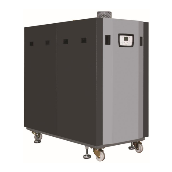
- Page 1 ONGAS 600 P FLOOR TYPE CONDENSING BOILER * ONGAS 604 P * ONGAS 609 P * ONGAS 605 P * ONGAS 610 P * ONGAS 606 P * ONGAS 611 P * ONGAS 607 P * ONGAS 612 P * ONGAS 608 P...
- Page 3 TABLE OF CONTENTS 1. General Information ..........................5 1.1. Introduction ........................... 5 1.2. Certificates ............................ 6 1.3.1. Explanations of the Symbols ..................... 6 1.3.2. General Warnings and Recommendations ................. 8 1.3.2.1. Points to be Considered During Handling and Transport ............8 1.3.3.
- Page 4 4.5. Operation of Control Panel Accessories ..................32 5. Installation and Inspection of the Piping ....................34 5.1. Heating (Radiator) Water......................34 5.1.1. Water Conditioning........................35 5.1.2. Water Pressure .......................... 35 5.2. Discharging of the Condensate ....................37 5.3. Instructions for the Adjustment of Gas Ratio ................37 5.3.1.
- Page 5 First of all, we would like to thank you for choosing the RIMA brand. In this manual, you will find installation and operation information for the RIMA branded floor type natural gas condensing heating boilers with aluminum cast fins manufactured by ÖNMETAL.
- Page 6 1.3.1.Explanations of the Symbols Warning Signs Safety Warnings are indicated with a warning triangle. Important information for the safety of persons are indicated with the symbol on the left 1.3.2.General Warnings and Recommendations • ONGAS 600 Series Floor Type Condensing Boilers with Aluminum Cast Fins are designed to be used in heating installations with domestic hot water and/or in domestic hot water installations and manufactured with the technology and materials suitable for this design.
- Page 7 • The cleaning of the installation is of utmost importance for the transformation projects from boilers with solid fuel or liquid fuel to boilers with gas fuel. The installation shall be washed, any leaks shall be detected and repaired and a plate type heat exchanger shall be used. •...
- Page 8 • Supply of cold water to the boiler shall be performed when the boiler is cold. • It is possible that oxygen may pass through the floor heating pipes into the water. Oxygen in the water causes corrosion of the boiler. Therefore, if the boiler is to be used in a floor heating system, a heat exchanger shall be added to the circuit and mixing of the boiler water and installation water shall be prevented.
- Page 9 1.3.4.Cascade Configuration The use of floor type condensing boilers in central systems is increasing every day. Condensing boilers designed for this purpose provide high capacities with low space requirement. An advantageous and economical heating is ensured by reaching a capacity of 760 kW in one boiler and a max. capacity of 12160 kW with a cascade system.
- Page 10 1.4.1.Points to Consider Before Contacting the Authorized Service First of all, we would like to thank you for choosing and using the “Rima Condensing Boiler”. Below is a list of things to do before calling the Rima Authorized Service. ...
- Page 11 All connections to be made on the electrical panel through the boiler shall be performed by Rima authorized service centers. If it is desired that the electrical installation is also performed by the authorized service, labor costs shall be subject to a charge to be determined by the service.
- Page 12 All gas devices shall be installed by qualified technicians. Any error in the installation of these devices may result in criminal actions as required. RIMA ONGAS 600p condensing boilers shall not be installed or modified in any way other than those specified in this manual. Always keep the boiler in its safety packaging during its transport before installation.
- Page 13 Packaging Label: 1.5.1. Parts Delivered as Standard with the Product Siphon Assembly Operating Manual Warranty Certificate Important: Operating instructions to ensure that the boiler may be used without any problem for many years are included in the operating manual. Gas Type Label The boiler is set for natural gas H/E (G20, 20 mbar) in the factory.
- Page 14 1.6.Data Label 2. GENERAL SPECIFICATIONS OF THE CONDENSING BOILER 2.1.Components of the ONGAS 600P Floor Type Condensing Boiler...
- Page 15 2.2. Technical Specifications of the Floor Type Condensing Boiler ONGA ONGAS ONGAS ONGAS ONGAS ONGAS ONGAS ONGAS ONGAS S 604 ONGAS 600P Serisi 605 P 606 P 607 P 608 P 609 P 610 P 611 P 612P Heat input (max) Heat input (min) Heat output (max) –...
- Page 16 3.1.Packaging and Handling ONGAS 600P Series condensing boilers are dispatched as covered with sheets coated with powder-static paint, wrapped with stretch film, on pallets and inside crates. Appropriate markings are provided on the case. During storage, it may be stored at proper ambient humidity and temperature without opening the package.
- Page 17 • Boilers shall not be installed in a location that contains moisture, vapor or dust. Otherwise the boiler shall not operate correctly and efficiently. • The floor of the installation location of the boiler shall be stable, firm and wide, and it shall be positioned high above the ground in order not to be affected by floods.
- Page 18 3.2. Dimensions of the Condensing Boiler Dimensions in “mm”...
- Page 19 3.3. Dismantling : 3.4.Gas Connections Gas connections shall be performed by authorized personnel or by installation companies with certification for gas installations. Sediments and collected particles in old installations, radiators or gas pipes shall be removed before installation. ...
- Page 20 Only the original RIMA spare parts and spare parts provided by the authorized local gas representative shall be used in the flue gas outlet connections. Please read the instructions before connecting the flue. Local gas distributors may have different directives, so obtain information from your local gas companies or their representatives 3.5.Electrical Connections...
- Page 21 3.6.Ongas 600 Electrical Wiring Diagram...
- Page 23 3.8 Commissioning The following instructions shall be followed to operate the unit. Correct installation, electrical installation, and in case of wireless solutions, correct radio connection with all required external units are prioritized. Make all hardware-specific settings. Be very careful when following the instructions provided on the “Configuration”...
- Page 24 4.OPERATION OF THE CONTROL PANEL 4.1. Control Panel Display: 4.2.Application Modes: 2.1.Selection of the Heating Mode Range: This setting is used for switching between different operating modes. Selection is indicated by the line under the relevant symbol. 2.1.1.Automatic Mode : Automatic mode controls the room temperature as per the time schedule.
- Page 25 Features of the continuous operation: • Heating mode without time schedule • Protective functions are active • 24-hour heating limit is not active at Automatic summer/winter switching (ECO functions) and Continuous operation with comfort level 2.1.3.Protection or Off: Heating system is off during the operation of the protection mode, but protection against frost (freezing protection temperature) is active if there is no power error.
- Page 26 DHW key Activation is performed by holding the DHW operating mode button on the room unit or operator for at least 3 seconds. It can may be started in the following conditions: • Operating mode is “Off” • When switching between the operating modes are active as H1 or centrally (LPB), •...
- Page 27 2.7.Possible Indicators: Some of the information lines listed below may not be displayed depending on the unit type, configuration, and operating status. Indicator: Possible error messages Possible service messages Possible special mode messages 2.8. Other Indicators: Room temperature ...
- Page 28 Reset Function; if resetting is permitted on the current operating line (end user/operating mode/heat engineer), the reset function for measurement devices and resettable parameters appears on the bottom line of the display. If manual operation is active, the relays are no longer supplied with power and their energy is cut off as per the control status, but they may be set to a predetermined manual operating status depending on their function.
- Page 29 Operating lines may not be displayed depending on user levels, controller types, and the configuration performed.
- Page 30 Sample Menu Structure 4.4.User Levels User levels allow only authorized user groups to make settings. To access the desired user level, perform the following steps;...
- Page 31 The password shall be entered to access the OEM level. Setting the “end-user” configuration User Menu and Line Numbers Date and time of the day (1-6) Operator unit (20-70) Wireless (120-140) Time schedule heating circuit 1 (500-516) ...
- Page 32 Cascade diagnostics (8100-8150) Heat generation diagnostics (8304-8570) Heat consumption diagnostics (8700-9058) Burner control (9500-9652) “Heat engineer” configuration setting Entering the Engineer Level...
- Page 33 4.5. Operation of the Control Panel Accessories (QAA75.. / QAA78… / AVS37..) Operating Elements Room Unit (Optional) Operator Unit Display Options Heating at comfort level - Information level active Heating at economy level - Programming active Heating at Freezing Protection value - Heating provisionally OFF Starting sequence –...
- Page 34 Information level active Programming active Heating provisionally OFF-ECO function OFF Vacation function active Circuit heating Maintenance/Special Operation Error message 5. INSTALLATION AND INSPECTION OF THE PIPING 5.1. Heating Radiator Water (Water Quality and Related Operations): Installation water shall be evaluated in the following subjects during the commissioning of the boiler: 1.
- Page 35 To prevent calcification, water used in the installations shall be softened. While there are various methods for this purpose, the most applicable one is to install a resin softening system to the installation. In addition, authorized services shall measure the hardness value of the installation water while commissioning the boiler and condition the water by adding a “chemical additive”...
- Page 36 5.1.2. Water pressure: In high buildings, the pressure may exceed 6 bar, particularly when the water is heated, and cause the relief valve on the boiler to open. In such a case, water with the lost amount shall be added to the installation. This reduces the effect of water conditioning previously performed, causing calcification or corrosion by oxygen.
- Page 37 shall be washed very well; and we strongly recommend the use of a plate heat exchanger instead of the balance vessel between the boiler and the installation. 5.2.Discharging of the Condensate Drain the condensate directly to the drainage with a pipe. Due to the acidity level of this water (pH 2-5) use pipes made of plastic material only for the (R 3/4”) connection pipe.
- Page 38 Press the Operating Mode Switching button on the control panel of the boiler for 3-5 seconds, as indicated by the red arrow, to put the boiler into test mode. When you press the “info” button again after waiting for 2-3 seconds, the display shall indicate (50%) and the boiler modulation speed shall be displayed.
- Page 39 611 -612 P Adjustment of the Gas Ratio: 5.4.Flue Connections The boiler is designed for the following flue configurations: Type B23: The boiler is designed to be connected to an open flue hole that shall exit vertically from the roof. The combustion air is directly taken from the room where the boiler is installed. In connection type B23, the room shall comply with the same installation requirements as approved for open flue boilers.
- Page 40 Horizontal flue passages shall have a minimum inclination of 3º in the direction of the boiler Joints and auxiliary flue accessories made of plastic for cascade and individual installations shall be gas and water proof; and they shall also allow horizontal passages (min. 5 cm discharge per meter) that are inclined towards the boiler for discharges that do not contain any condensate.
- Page 41 5.5. Wiring Diagrams...
- Page 42 6.ERROR CODES Error code LPB code Error Definition Priority Ambient temperature sensor error boiler temperature sensor 1 error boiler temperature sensor 1 error boiler temperature solid fuel sensor error Common flow temperature sensor error Flue gas temperature sensor error Flue gas temperature sensor error Flow temperature sensor 1 error Flow temperature cooling sensor 1 error Flow temperature sensor 2 error...
- Page 43 Error code LPB code Error Definition Priority Storage tank temperature 2 (bottom) sensor error Storage tank temperature 3 (center) sensor error Collector temperature sensor 1 error Water pressure sensor error Water pressure sensor error LPB address conflict BSB cable cross sectional connection not available BSB cable address conflict BSBKF communication error...
- Page 44 Error code LPB code Error Definition Priority Water pressure too high Water pressure too low Water pressure too low Water pressure switch deactivated Water pressure switch deactivated Heating circuit 1 could not reach the flow temperature Heating circuit 2 could not reach the flow temperature Maximum boiler temperature exceeded Domestic water filling temperature not...
- Page 45 Error code LPB code Error Definition Priority Parameter error Unit locked manually Fan speed threshold not reached Air pressure switch does not turn off Flow / pressure switch, heating circuit error Flow / pressure switch, heating circuit error Air pressure switch error, it does not open Sitherm Prosystem error Sitherm Prosystem error Sitherm Prosystem error...
- Page 46 Error code LPB code Error Definition Priority Max. refilling period per filling operation is exceeded Max. refilling period per filling operation is exceeded Max. refilling period per week is exceeded Max. refilling period per week is exceeded Heating circuit error Heating circuit error Motor monitoring Fan air mixing valve error...
- Page 47 Error code LPB code Error Definition Priority Water pressure 3 too high Water pressure 3 too high Water pressure 3 too high BX inlet identical sensors BX inlet/auxiliary module identical sensors BX inlet mixture assembly identical sensors Auxiliary module identical function Mixture assembly identical function Auxiliary module/mixture assembly identical function...
- Page 48 Error code LPB code Error Definition Priority Solid fuel boiler address error Balance tank return valve Y15 missing Balance tank address error Main control unit system pump adress error Pressureless height address error Cascade winter sensor B10 missing Flow temperature heating circuit 3 Temperature limiting heating circuit 2 Auxiliary module 3 Sitherm Pro calculation...
- Page 49 • The power shall be disconnected from the mains switch for maintenance and cleaning operations. • Original spare parts recommended and provided by RIMA shall always be used for maintenance and repair operations.
- Page 50 • Periodical and annual maintenances of the boiler shall be performed regularly. • Repair and maintenance operations of ONGAS 600 series boilers require expertise. This guide explains the operation and maintenance procedures that shall be performed by the user. Other than these operations, the user or any person without the expertise shall not temper with any part or the settings of the boiler for reasons such as operating or maintaining, etc.
- Page 51 7.2.Cleaning of the Modulated Fan, Venturi and the Burner Remove the electrical connections from the fan, gas valve and the electrodes. 1. Remove the bolts on the exterior of the burner. 2. Clean the Premix burner with an air gun (the distance between the nozzle and burner shall be about 1 cm and the pressure of the compressed air shall be 2 –...
- Page 52 - Exceeding of the maximum time allowed for repair, - In the event that repair is not possible is determined by the authorized service station, seller, manufacturer or importer with a report. The seller is not allowed to reject the request of the consumer. The seller, the manufacturer and the importer are jointly liable if this request is not fulfilled 6) The repair period of the goods shall not exceed 20 working days.
- Page 53 8.1. Rima Condensing Boiler Commissioning Form...
- Page 54 The bottom and top ventilation requirements determined by the local gas office shall be followed. Ventilation vents shall not be closed. 2. Authorized boiler personnel should be provided with training on boiler operation by Rima authorized service during commissioning.
- Page 55 IMPORTANT: For the long-lasting and efficient operation of your boilers, have them maintained by the authorized …… service periodically at least once a year. IMPORTANT: Contact Rima authorized service in case of a fault. Central Contact: 0212 485 48 74...
- Page 56 8.3 Operating Instructions...
- Page 57 Edirne Org. San. Böl. 4. Cad. No:3-5 Domurcalı/ Süloğlu/ EDİRNE Tel: 0284 316 20 40 To get information on subjects related with sales; Rima Isı Sis. San. A.Ş. İkitelli OSB Mah. 25. Cad. No:10 Başakşehir/İSTANBUL Tel: 0212 485 48 74 To get information on after-sales services;...
- Page 58 All rights are reserved. Rima reserves the right to make changes on all their products without giving prior information.
Need help?
Do you have a question about the ONGAS 600 P Series and is the answer not in the manual?
Questions and answers