
Related Manuals for Rima ONGAS 300/W Series


Summary of Contents for Rima ONGAS 300/W Series
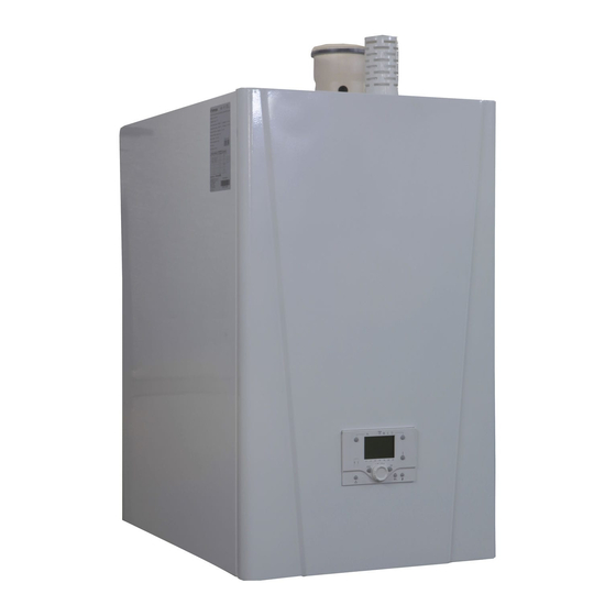
- Page 1 ONGAS 300/W SERIES CONDENSING BOILER Cast Aluminum Wall Hung Condensing Boilers · For Natural Gas · 0051 - 11...
- Page 2 Adjustment of the Gas Rate ( ONGAS 306/W & 307/W ) Adjustment of the Gas Rate ( ONGAS 303/W & 304/W & 305/W ) Chimney Connections Chimney Installation for ONGAS 300/W Series Example Hydraulic Schemes for ONGAS 300/W Series Fault Finding Description of the error codes Cleaning and Maintenance...
- Page 3 Terminal box (ONGAS 300/W Series )High Voltage Indicates possible danger of electric shock. Serious personal injury may occur. This boiler is connected to a 230v mains supply.
- Page 4 All gas appliances must be installed by authorized technicians. Failure to install appliances correctly could lead to prosecution. RIMA ONGAS300/W condensing boiler must not be installed or modified in any situations except written in this manual. Always transport the boiler in the safety packaging , before installation. Additional protection may be required if site conditions warrant it –...
- Page 5 If not , there is suffocate and poisoning risk . Read the technical instructions before installing and lighting the boiler. ONGAS 300/W Series Wall Hung Condensing Boilers for Natural Gas Operating Principle of ONGAS 300/W Series...
- Page 6 Operating Instructions...
- Page 12 All main electrical and electronically controls are supplied in the control panel which is placed on top of the boiler. The RIMA ONGAS 300/W series condensing boiler is suitable for room sealed or open flue applications (B and C type) and has been designed for central heating also optionally domestic hot water.
- Page 13 Installation Instructions RIMA ONGAS 300/W Series Condensing Boiler should be positioned as follows ; Place the boiler in the plant room to operation location. Remove films, straps, pallets, top and sides and all other packaging. All gas appliances must, by law, be installed by authorized persons. Failure to install appliances correctly could lead to prosecution.
- Page 14 · valve between boiler and safety valve, otherwise pipes and the other parts may explode in the over- pressurized boiler (evaporation harmless). RIMA ONGAS 300/W Series Condensing Boilers are only compatible and works with systems which has · circulation pump.
- Page 15 Lime and chalk can be formed according to the working type of boiler. Radiators must be heated in min. efficiency with enough water flow. In cascade systems, all boilers must be worked same capacity, otherwise chalk and lime may condensed in one boiler. All plumbing system pipes must be check against leakage before operating the boiler.
- Page 16 Measuring Point Gas Inlet In the flue gas discharge connections, only RIMA Original Parts and authorized local gas dealer parts must · be used. Please read carefully instructions before connecting the chimney. Local gas distributers may have different directives, because of this, information should be taken from local ·...
- Page 17 Electrical Connection Samples Remove the screws from control panel for connecting electrical supply and other equipments. Safety Thermostat Energy ON/OFF Working Indicator Switch Indicator Terminal Connections Mainboard Terminal Box To ensure reliable long term operation, mount the boiler control at a position in the appliance with ·...
- Page 18 The modulation function of the boiler control units is checked during the start up safety check. As · a result the gas technical safety of the appliance provided with a boiler control unit can rely on the proper functioning of the adjustable gas outlet pressure during ignition of this boiler control unit. This means that due to a safe ignition pressure level, the safety time of the boiler can be extended.
- Page 19 ONGAS 300 Series Electrical Wiring Diagram All electrical connections must be done according the diagrams are given above.
- Page 20 Cascade Configurations The boiler is also suited for configuration in a cascade applications. For overpressure flue gas cascade arrangements, use our motorized flue gas discharge valve (available as an accessory). This prevents flue gas from flowing back to boilers that are not in operation. As a result of the narrow width and depth of the boiler, a heat output of 375 kW (2 x ONGAS 307/W ) can be provided in a floor area of just under 2 m2.
- Page 21 Adjustment of the Gas Rate ONGAS 306/W & 307/W ( VR 425 Series Gas Valve ) The boiler must be run at full modulation rate mode before starting the adjustment, therefore the boiler must be set test mode by using LCD display.
- Page 22 ONGAS 304/W & 305/W ( VR 4615 Series Gas Valve ) Repeat the mentioned steps above by using proper tool as it is shown picture (use screw driver for maximum gas rate adjustment) . ONGAS 303/W ( VK 4115 Series Gas Valve ) Repeat the mentioned steps above by using proper tool as it is shown picture ( use Allen tool for maximum gas rate adjustment) .
- Page 23 Chimney connections The boiler has been approved for the following flue configurations: Type B23 Boiler designed to be connected to an open flue which will terminate vertically through the roof. The combustion intaken directly from room where boiler installed. B23 type of connection the room must comply with the same installation regulations valid for open chimney boilers.
- Page 24 2 meters must be supported independently and may not rest on the boiler. The flue outlet should terminate with reduction cone and bird guard only. Chimney Installation for ONGAS 300/W Series 1- ONGAS 300/W Series Condensing Boiler 2- Chimney Clamp...
- Page 25 ONGAS 300/W Series Example Hydraulic Schemes Scheme -1 Meaning of the symbols on Scheme-1 DHS: Outside Temperature Sensor KP: Circulation Pump DKS: Low Loss Header sensor AP: Main Pump Note: 1. Only general installation princple,and electrical sensors are shown in the scheme. Filters, valves and expansion vessels are not shown in the scheme., these components must be choosen and placed accordingly.
- Page 26 Scheme -2 Meaning of the symbols on Scheme-2 DHS: Outside Temperature Sensor KP: Circulation Pump DKS: Low Loss Header sensor BS: Boiler Sensor IP: Heating pump BP: Boiler Pump Note: 1. Only general installation princple,and electrical sensors are shown in the scheme. Filters, valves and expansion vessels are not shown in the scheme., these components must be choosen and placed accordingly.
- Page 27 Scheme -3 Meaning of the symbols on Scheme-3 DHS: Outside Temperature Sensor KP: Circulation Pump DKS: Low Loss Header sensor BS: Boiler Sensor UYV : 3 way valve AP : Main pump Note: 1. Only general installation princple,and electrical sensors are shown in the scheme. Filters, valves and expansion vessels are not shown in the scheme., these components must be choosen and placed accordingly.
- Page 28 Fault Finding...
- Page 31 Cleaning and Maintenance The boiler is virtually maintenance free; it only has to be inspected once a year and only if necessary be serviced/cleaned. The annual inspection of the boiler includes: - combustion system check of the boiler ( Clean the fan, venturi and burner ); - checking the ignition electrode;...
- Page 32 Combustion System Check Combustion is checked by measuring the O percentage in the flue gas discharge duct. To do this, heat the boiler to a water temperature of ~ 70°C. The measurements must meet the values set according to gas rate adjustments. The flue gas temperature can also be measured at the measuring point in the flue gas discharge duct.
- Page 33 Checking the electrodes Check the ignition electrode adjustment (between 3 and 3,5 mm) and replace electrode if necessary (including sealing). Also check the electrode's porcelain for hairline fractures because this may cause spark-over. Flame Sensing Electrode 3 – 3,5 mm Ignition Electrode Commissioning Form Commissioning Steps...
Need help?
Do you have a question about the ONGAS 300/W Series and is the answer not in the manual?
Questions and answers