Advertisement
Quick Links
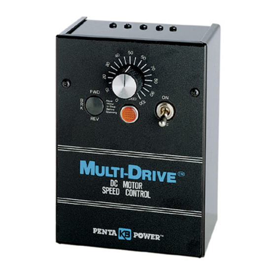
KBMD-240D
MULTI-DRIVE
Variable Speed DC Motor Control
For Shunt Wound and PM Motors
Patented Overload Circuit
1/100 – 1 Hp @ 115 VAC – 50/60 Hz
1/50 – 2 Hp @ 230 VAC – 50/60 Hz
TYPICAL APPLICATIONS
• Conveyors • Packaging Machines
• Feeders • Printing Equipment
STANDARD FEATURES
•
Plug-in Horsepower Resistor
used on a wide range of motors.
•
Dual Voltage Switch. Used to select AC line voltage
operation of 115 or 230V.
•
Built-in AC Line Fuse
•
MOV Transient Protection (20 JOULE)
•
Trimpots: MIN, MAX, IR, CL, ACCEL, DECEL
PHR Supplied Separately
OPTIONAL FEATURES
•
Auxiliary Heatsink (P/N SC-9861). Extends control rating to
1 Hp at 115V and 2 Hp at 230V.
•
Forward-Brake-Reverse Switch (P/N SC-9860). Includes
switch and prewired dynamic brake resistor.
SPECIFICATIONS
Speed Range (Ratio) ...................................................... 50:1
Load Regulation
(0 – Full Load, 50:1 Speed Range) (% Base Speed)...... 1*
Line Voltage Regulation
(At Full Load, ± 15% Line Variation) (% Base Speed) .... 1/2*
Control Linearity
(% Speed vs. Dial Rotation) .............................................. 2
CL/Torque Range
(% Full Load) .......................................................... 0 – 200
ACCEL/DECEL Time (Secs.) ...................................... .2 – 10
MIN Speed Trimpot Range
(% Full Speed) ........................................................ 0 – 30*
MAX Speed Trimpot Range
(% Full Speed) .................................................... 50 – 120*
Maximum Allowable Ambient Temperature
(At Full Rating, °C/°F) .............................................. 40/105
Rating indicated is with Auxiliary Heatsink. Maximum rating without Auxiliary
Heatsink is 1/2 Hp at 115V and 1 Hp at 230V.
* Performance is for 90V PM motors on 115 VAC and 180V PM motors on 230 VAC.
* CE Compliance Requires KBRF-200A RFI Filter
38
TM
®
®
. Allows a single model to be
A Complete Line of Motor Drives
*
Multi-Drive™ represents the latest in state-of-the-art
design for variable speed DC motor controls. It is rugged
and compact is size and is able to handle both 115 and
230V AC line inputs by setting the built-in Dual Voltage
Switch. In addition, the single model can be used on a
wide range of motors by selecting and inserting the
appropriate Plug-in Horsepower Resistor
The standard model, KBMD-240D, controls all
motors through
3
⁄
Hp at 115V and 1
4
installing the KB Auxiliary Heatsink, the horsepower
range is increased to 1 Hp at 115V and 2 Hp at 230V.
The versatility of the control is enhanced with the optional
Forward-Brake-Reverse Switch Kit.
The electronics for the Multi-Drive™ consists of KB's
patented KBMM™ speed control module. Its field-proven
reliability is confirmed by over 100,000 controls presently
in operation. The KBMM™ module is housed in a rugged
metal (not plastic, like other inexpensive drives) enclosure.
Keyhole slots facilitate mounting while a readily accessible
terminal block simplifies wiring. Included with each control
is a detailed instruction and user manual.
WIRING DIAGRAM
A-
A+
F-
ARMATURE
*Use for shunt motors only.
DATA SHEET D-325
DESCRIPTION
®
.
1
⁄
Hp at 230V. By
2
F+
L1
L2
AC
FIELD*
LINE
TM
Rev.______(A_______)
P/N 9370
GROUND
Advertisement

Related Manuals for Penta KB Power MULTI-DRIVE KBMD-240D

Summary of Contents for Penta KB Power MULTI-DRIVE KBMD-240D
- Page 1 DATA SHEET D-325 KBMD-240D MULTI-DRIVE Variable Speed DC Motor Control For Shunt Wound and PM Motors Patented Overload Circuit 1/100 – 1 Hp @ 115 VAC – 50/60 Hz 1/50 – 2 Hp @ 230 VAC – 50/60 Hz TYPICAL APPLICATIONS •...
- Page 2 FEATURES & FUNCTIONS (1) Rugged all aluminum enclosure (2) Keyhole slots facilitate mounting (3) AC Power Indicator (4) ON/OFF Power Switch (5) Speed Control Knob (6) Auxiliary Heatsink (optional) (7) FWD-BRK-REV Switch (optional) (8) Dual Voltage Switch (“115" or “230") (9) AC Line Fuse Included (10) Plug-in Horsepower Resistor ®...
- Page 3 KBMD DC MOTOR SPEED CONTROL PLUG-IN HORSEPOWER RESISTOR® (PHR) QUICK-START INSTRUCTIONS The PHR is supplied by your distributor and must be installed for the control to operate. It is used to automatically calibrate the IR Compensation and Current Limit based on motor horsepower and voltage. It eliminates the need to recalibrate the FOR TECHNICAL ASSISTANCE control in most applications.
- Page 4 ADJUSTABLE TRIMPOTS OPTIONAL ACCESSORIES The control contains trimpots which have been factory set ACCEL TRIMPOT Auxiliary Heat Sink (Part No. 9861): Increases the horsepower rating of the control for most applications. Some applications may require from 3/4 HP (0.56 kW) to 1 HP (0.75 kW) on 90 – 130 Volt DC motors) and from readjustment of the trimpots in order to tailor the control for a 1½...
- Page 5 DATA SHEET D-500 KBWM VARI-DRIVE NEMA-1 SCR Variable Speed DC Motor Control For Permanent Magnet (PM), Shunt Wound Motors and Magnetic Particle Clutches TWO MODELS COVER 1/100 - 1/3 Hp @ 90VDC ® 1/50 - 3/4 Hp @ 180 VDC •...
- Page 6 ELECTRICAL RATINGS Model KB Part Input Line Voltage Armature Maximum AC Load Maximum DC Load Maximum Power (Hp) [KW] Number (VAC - 50/60 Hz) Voltage (VDC) Current (RMS AMPS) Current (DC Amps) KBWM-120 9380 0 - 90 1/3 [.25] KBWM-240 9381 0 - 180 3/4 [.50]...
- Page 7 INSTALLATION AND OPERATING INSTRUCTIONS RIVE NEMA 1 / IP20 SCR Variable Speed DC Motor Controls Model KBWM-120 rated 1/100 - 1/3 HP (90 Volts DC) @ 115 Volts AC, 50/60 Hz Model KBWM-240 rated 1/50 - 3/4 HP (180 Volts DC) @ 208/230 Volts AC, 50/60 Hz ARI- RIVE DC MOTOR SPEED CONTROL...
- Page 8 TABLE OF CONTENTS Section Page Simplified Operating Instructions ......... . 1 Safety Warning .
- Page 9 KBWM-120, 240 SIMPLIFIED OPERATING INSTRUCTIONS IMPORTANT – You must read these simplified operating instructions before proceeding. These instructions are to be used as a reference only and are not intended to replace the detailed instructions provided herein. You must read the Safety Warning before proceeding. A.
- Page 10 This product complies with all CE directives pertinent at the time of manufacture. Contact factory for detailed installation and Declaration of Conformity. Installation of a CE approved RFI filter (KBRF-200A [P/N 9945C] or equivalent) is required. Additional shielded motor cable and/or AC line cables may be required along with a signal isolator (KBSI-240D [P/N 9431] or equivalent).
- Page 11 TABLE 2 – ELECTRICAL RATINGS Max. AC Max. DC Input Voltage Armature Max. Horsepower Model No. Part No. Load Current Load Current (VAC - 50/60 Hz) Voltage (VDC) HP, (kW) (RMS Amps) (DC Amps) KBWM-120 9380 0 – 90 1/3, (0.25) 0 –...
- Page 12 FIGURE 2 – MECHANICAL SPECIFICATIONS (Inches / [mm]) TOP VIEW BOTTOM VIEW...
- Page 13 CONTROL SETUP Remove the four (4) 6x32 screws (two on top and two on the bottom) from the enclosure. Slide open the control by separating the front and rear covers. See Figure 2, page 4. A. Plug-in Horsepower Resistor® – (Must be obtained from your distributor as a separate part.) The Plug-in Horsepower Resistor®...
- Page 14 FIGURE 3 – MOTOR VOLTAGE SELECTION D. Jumper J2 is provided on Model KBWM-240 only (MODEL KBWM-240 ONLY) and is factory set to “180V” position. For step- down operation (208/230 Volts AC line input and 0- J2 Set for J2 Set for 90 Volts DC output), set J2 to the “90V”...
- Page 15 Caution: If control is wired to a transformer, it is advisable to switch the secondary to dis- connect power. If the primary is switched, additional snubber capacitors may have to be added across terminals L1 and L2 to prevent power bridge damage. Separate branch fusing or circuit breaker may be required on 208/230 VAC applications.
- Page 16 E. Fusing – As indicated in Section IIB, the KBWM™ contains a single AC line fuse on 208/230 VAC applications. In the USA and other countries where the 208/230 volt is derived from two (2) “hot” leads, both AC lines should be connected to a separate dual cir- cuit breaker.
- Page 17 FIGURE 6A – ACCEL TRIMPOT ADJUSTMENT A. Acceleration Start – The ACCEL is factory set at approximately 2 seconds. FACTORY SETTING 2 SEC. To readjust to different times, set the knob to the desired position as shown in Figure 6A. RAPID B.
- Page 18 Note: If only an AC ammeter is available, it can be installed in series with AC input line. Follow above instructions; however, set AC amperage at 0.75 motor rating. F. IR Compensation Adjustment – IR compensation is provided to improve load regulation. If the load presented to the motor does not vary substantially, the IR adjustment may be set at a minimum level (approximately 1/4 of full setting).
- Page 19 FIGURE 7 – INTERNAL CONNECTION DIAGRAM 180V...
- Page 20 – NOTES –...
- Page 21 – NOTES –...
- Page 22 VII. LIMITED WARRANTY For a period of 18 months from the date of original purchase, KB Electronics, Inc. will repair or replace, without charge, devices which our examination proves to be defective in material or workmanship. This warranty is valid if the unit has not been tampered with by unauthorized persons, misused, abused, or improperly installed and has been used in accordance with the instructions and/or ratings supplied.
Need help?
Do you have a question about the MULTI-DRIVE KBMD-240D and is the answer not in the manual?
Questions and answers