Table of Contents
Advertisement
KBIC
Solid State SCR
DC Motor Speed
Controls
See table 2 page 4 for KBIC
models covered by this manual
Patented Ultra Fast
CL Circuit Prevents
Demagnetization in
PM Motors
Installation and
Operating
Instructions
See SAFETY WARNING on page 4
Section
Safety Warning . . . . . . . . . . . . . . . . . . . . . . . . . . . . . . . . . . . . . . . . . . . . . . . . . . . . . . . . . . . . . . . . . . . . . . . . . . . .
ii.
Simplified Instructions . . . . . . . . . . . . . . . . . . . . . . . . . . . . . . . . . . . . . . . . . . . . . . . . . . . . . . . . . . . . . . . . . . . . . . . . 3
iii. Introduction . . . . . . . . . . . . . . . . . . . . . . . . . . . . . . . . . . . . . . . . . . . . . . . . . . . . . . . . . . . . . . . . . . . . . . . . . . . . . . .
I.
Application Information . . . . . . . . . . . . . . . . . . . . . . . . . . . . . . . . . . . . . . . . . . . . . . . . . . . . . . . . . . . . . . . . . . . . . .
II.
Installation Instructions . . . . . . . . . . . . . . . . . . . . . . . . . . . . . . . . . . . . . . . . . . . . . . . . . . . . . . . . . . . . . . . . . . . . . .
III. Adjustments & Control Functions . . . . . . . . . . . . . . . . . . . . . . . . . . . . . . . . . . . . . . . . . . . . . . . . . . . . . . . . . . . . .
IV. Switching Circuits . . . . . . . . . . . . . . . . . . . . . . . . . . . . . . . . . . . . . . . . . . . . . . . . . . . . . . . . . . . . . . . . . . . . . . . . .
V. Limited Warranty . . . . . . . . . . . . . . . . . . . . . . . . . . . . . . . . . . . . . . . . . . . . . . . . . . . . . . . . . . . . . . . . . . . . . . . . . .
1.
Nominal Trimpot Settings . . . . . . . . . . . . . . . . . . . . . . . . . . . . . . . . . . . . . . . . . . . . . . . . . . . . . . . . . . . . . . . . . . . .
2.
Electrical Ratings . . . . . . . . . . . . . . . . . . . . . . . . . . . . . . . . . . . . . . . . . . . . . . . . . . . . . . . . . . . . . . . . . . . . . . . . . . . 4
3.
General Performance Specifications . . . . . . . . . . . . . . . . . . . . . . . . . . . . . . . . . . . . . . . . . . . . . . . . . . . . . . . . . . .
4.
Fuse Selection Chart . . . . . . . . . . . . . . . . . . . . . . . . . . . . . . . . . . . . . . . . . . . . . . . . . . . . . . . . . . . . . . . . . . . . . . .
5.
6.
Minimum Supply Wire Requirements . . . . . . . . . . . . . . . . . . . . . . . . . . . . . . . . . . . . . . . . . . . . . . . . . . . . . . . . . . .
7.
Field Connections . . . . . . . . . . . . . . . . . . . . . . . . . . . . . . . . . . . . . . . . . . . . . . . . . . . . . . . . . . . . . . . . . . . . . . . . . .
8.
Parts List . . . . . . . . . . . . . . . . . . . . . . . . . . . . . . . . . . . . . . . . . . . . . . . . . . . . . . . . . . . . . . . . . . . . . . . . . . . . . . . .
®
1.
Basic KBIC
. . . . . . . . . . . . . . . . . . . . . . . . . . . . . . . . . . . . . . . . . . . . . . . . . . . . . . . . . . . . . . . . . . . . . . . . . . . . . .
2.
Mechanical Specifications . . . . . . . . . . . . . . . . . . . . . . . . . . . . . . . . . . . . . . . . . . . . . . . . . . . . . . . . . . . . . . . . . . .
3.
Connection Diagrams . . . . . . . . . . . . . . . . . . . . . . . . . . . . . . . . . . . . . . . . . . . . . . . . . . . . . . . . . . . . . . . . . . . . . . .
4.
ACCEL Trimpot Adjustment . . . . . . . . . . . . . . . . . . . . . . . . . . . . . . . . . . . . . . . . . . . . . . . . . . . . . . . . . . . . . . . . .
5a. Master/Slave Circuit . . . . . . . . . . . . . . . . . . . . . . . . . . . . . . . . . . . . . . . . . . . . . . . . . . . . . . . . . . . . . . . . . . . . . . .
5b. Dynamic Brake Circuit . . . . . . . . . . . . . . . . . . . . . . . . . . . . . . . . . . . . . . . . . . . . . . . . . . . . . . . . . . . . . . . . . . . . .
5c. Overload Protection . . . . . . . . . . . . . . . . . . . . . . . . . . . . . . . . . . . . . . . . . . . . . . . . . . . . . . . . . . . . . . . . . . . . . . .
6.
Schematic . . . . . . . . . . . . . . . . . . . . . . . . . . . . . . . . . . . . . . . . . . . . . . . . . . . . . . . . . . . . . . . . . . . . . . . . . . . . . . .
2
®
®
A COMPLETE LINE OF MOTOR DRIVES
TABLE OF CONTENTS
TABLES
®
Chart . . . . . . . . . . . . . . . . . . . . . . . . . . . . . . . . . . . . . . . . . . . . . . . . . . . . . . . . . . .
FIGURES
®
Basic KBIC
PATENTED
*See Page 3
™
©1996 KB ELECTRONICS, INC.
Page
3
6
6
7
10
11
16
3
4
5
5
8
8
15
5
7
8
10
12
13
13
14
Advertisement
Table of Contents

Related Manuals for Penta KB Power KBIC-120

Summary of Contents for Penta KB Power KBIC-120
-
Page 1: Table Of Contents
® KBIC Solid State SCR DC Motor Speed Controls ® See table 2 page 4 for KBIC models covered by this manual Patented Ultra Fast CL Circuit Prevents Demagnetization in PM Motors Installation and ® Basic KBIC Operating Instructions PATENTED See SAFETY WARNING on page 4 *See Page 3 ™... -
Page 2: Safety Warning
Motor Only) (VDC) Load Current Load Current Load Current Load Current 50/60Hz (VDC) (RMS Amps) (Avg. Amps) (RMS Amps) (Avg. Amps) KBIC-120 0 - 90 18.0 12.0 50, 100 KBIC-125 0 - 90 12.0 0.75 24.0 16.0 50, 100 KBIC-240 0 - 180 18.0... -
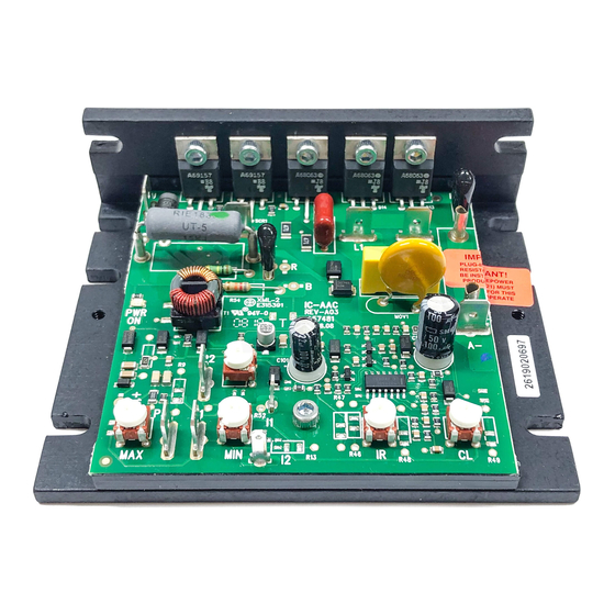
Page 3: Introduction
® *Note: Specific applications may require a different fuse value than FIG. 1 – BASIC KBIC indicated. This is based on several factors such as ambient temperatures, duty cycle, motor form factor and CL setpoint. FIG. 1 – FEATURES AND FUNCTIONS (1) Plug-in Horsepower Resistor ®... -
Page 4: Minimum Supply Wire Requirements
FIG. 2 – MECHANICAL SPECIFICATIONS POTENTIOMETER OPTIONAL AUXILIARY HEATSINK 0.982 0.500 CONTROL 1/4" ROUND ALUM. SHAFT 5.625 7.000 3/8-32 ANTI- BUSHING 3.110 ROTATION 5.625 6.250 0.125 1.250 .438 1.375 DWG #:D2600-1-00281 II. INSTALLATION INSTRUCTIONS ® Location and Mounting – The KBIC controls should be mounted on a flat surface and located in an area where it will not be exposed to contaminants such as water, metal chips, solvents or excessive vibration. -
Page 5: Accel Trimpot Adjustment
WARNING: If control is wired to a transformer, do not switch the primary side of transformer to disconnect power or catastrophic failure can result. Always disconnect control from secondary side of transformer. CAUTION: Do not bundle potentiometer connections (P1, P2, P3) and Inhibit™ connections (I1, I2) with AC line or motor wires. WARNING: Armature Switching. - Page 6 Note: The MIN speed adjustment will affect the MAX speed setting. Therefore, it is necessary to readjust the MAX speed after the MIN speed, and it may be necessary to repeat the sequence until both the MIN and the MAX speeds are set to the desired levels.
- Page 7 FIG. 5B – DYNAMIC BRAKE CIRCUIT (Using Inhibit™) Notes (Dynamic Brake Circuit) * Choose RB resistance and wattage according to braking requirements. ** Inhibit™ circuit extinguishes output of control during brake. When the armature is reenergized, the Inhibit™ releases which allows for a smooth start. C.
Need help?
Do you have a question about the KBIC-120 and is the answer not in the manual?
Questions and answers