Advertisement
BEFORE USE
This section must be read before connecting to the mains supply
MAINS CONNECTION INFORMATION
Your SUGDEN amplifier has been designed to comply with the domestic power and safety requirements that exist in your area. This amplifier can be powered by AC ONLY.
IF YOU NEED TO ADJUST THE GAIN SETTING OF YOUR AMPLIFIER TO MATCH YOUR CARTRIDGE YOU MUST ALWAYS DISCONNECT THE MAINS LEAD FROM THE MAINS SUPPLY.
CHOOSE A SAFE AND SUITABLE LOCATION
Your amplifier is a class A design and therefore requires good ventilation
DO NOT: Expose to direct Sunlight
DO NOT: Position next to a heat source such as a radiator
DO NOT: Use in places with high humidity of poor ventilation DO NOT: Subject to mechanical vibration
DO NOT: Place on an unstable or inclined surface
DO NOT: Stand other equipment on top of the amplifier
Never block the ventilation holes or stand directly on a carpet
UNPACKING
Your amplifier should reach you in a substantial protective carton. On unpacking please examine the unit for signs of prior use or damage. Check that all the front panel controls function mechanically.
INSTALLATION
Do not stand the unit in direct sunlight or near a heat source such as a central heating radiator.
ACCESSORIES SUPPLIED
- IEC straight connector with moulded mains plug. This should be suitable for your country. To check that the pre-amplifier is the correct voltage examine the carton, the assembly ticket attached to rear of the unit and the legend on the rear of the unit.
- Three pin L.T. (low tension) power lead
CONNECTING YOUR PHONO AMPLIFIER TO THE MAINS SUPPLY
Use the IEC power chord supplied, as this has been properly tested and EC approved to be used with your phono amplifier. The mains input socket is located at the rear of the PSU (power supply unit) and is clearly marked 'mains input '. It is normal to leave the amplifier mains power on unless being left unattended for a long period of time.
FUSES
If a fuse does blow this is usually an indication that a fault has occurred. ALWAYS DISCONNECT YOUR EQUIPMENT FROM THE MAINS SUPPLY IF YOU ARE REPLACING A FUSE. There are two fast blow fuses located on the main circuit board of the PSU. These must only be replaced by ones of the same specification, FAST BLOW. If in any doubt please contact your supplier. Replacing these fuses with ones of a different value and specification may damage the equipment or not survive the inrush current on switch on. A Mains input fuse (T antisurge) is located in a tray below the mains input socket. This tray also contains a spare fuse of the correct value and type.
INSTRUCTIONS FOR USE
MAINS SWITCH AND INDICATOR
The mains switch is located at the rear of the PSU and switches the amplifier on, when operational the red LED on the front of the PSU will light up.
CONNECTING THE L.T POWER SUPPLY
The Stage Two is a twin box system separating the phono amplifier from the low-tension power supply. This helps reduce pickup and interference. Use the three-pin (L.T) lead supplied to connect the power supply to the phono amplifier. Never remove or insert the L.T lead when connected to the mains supply.
CONNECTING YOUR PHONO AMPLIFIER TO A PRE-AMPLIFIER
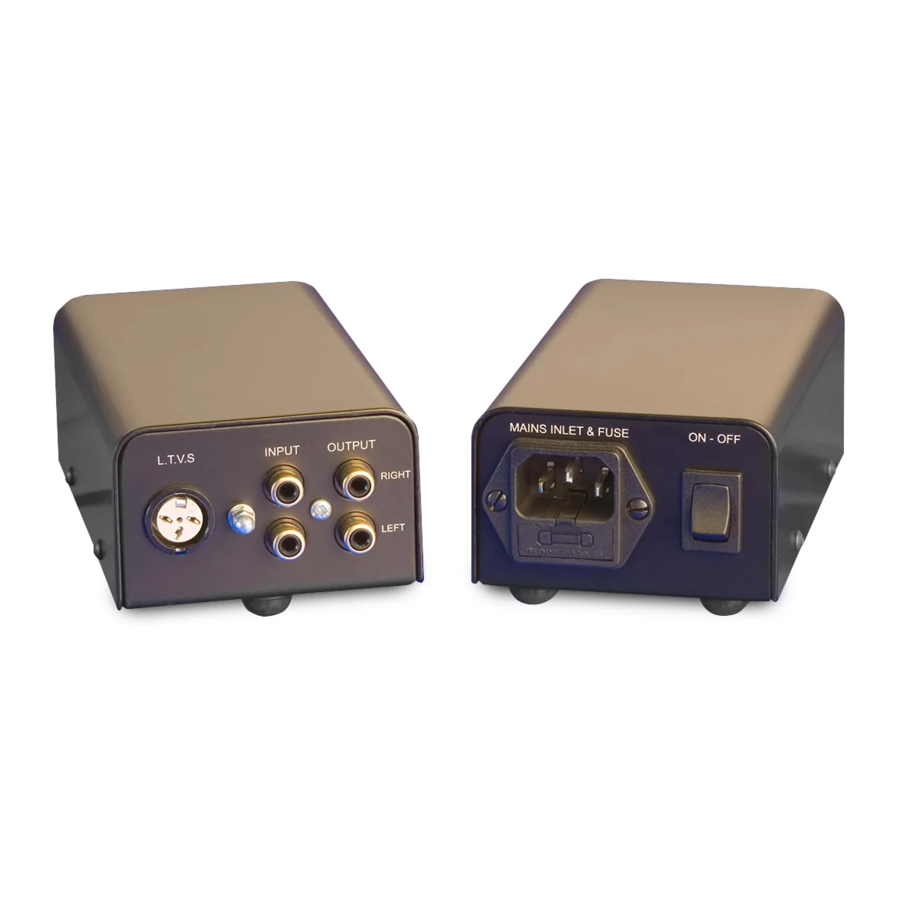
The Stage Two has a pair of output phono sockets; these phono sockets are standard type RCA connectors with gold plated contacts. It is advisable to make sure your interconnect leads have similar quality plugs that fit securely. We recommend WBT type connectors preferably the locking type. These offer the best possible connection. The phono sockets are clearly marked right and left for identical connection to your pre-amplifier. Do not insert or remove the leads with the equipment switched on.
CONNECTING YOUR TURNTABLE TO THE PHONO AMPLIFIER
Your Phono amplifier is well equipped and will accept either MM or MC cartridges. The single set of input sockets is clearly marked on the back panel. The inputs are marked right and left for identical connection to your turntable arm cable. Do not remove or insert the leads when the equipment is switched on.
CARTRIDGE LOADING
We recommend that you experiment with cartridge loading as some popular music can sound compressed on a wide-bandwidth audio system. Well-recorded classical and jazz music normally sounds at its best with the correct loading.
The standard factory setting of the Stage two Is Moving Magnet (MM) 47K. Most MM cartridges require a loading of 47K.
Moving Coil (MC) cartridges normally require loading of >20 Ohms with the most common being 100 or 470 Ohms. To change the factory setting to either of these loads and to MC, you need to remove the outer case of the phono amplifier. To do this you will require an M3 Allen key suitable for a socket set screw. BEFORE REMOVING THE OUTER CASE DISCONNECT FROM THE PSU.
The two loads are selected by a pin and jumper system that are clearly labelled on the circuit board:
| Factory set MM | No adjustment |
| Low output moving coil | J3 and J6 |
| 100 Ohms | J1 and J4 |
| 470 Ohms | J2 and J5 |
These settings are also printed on the base of the Phono amplifier for quick reference.
SWITCH ON
As the PhonoMaster is a high-gain piece of equipment it is advised that this should be switched on first to avoid any surges being amplified by the main power amplifier.
SET-UP AND FINE TUNING
The design of the A21SE Stage Two is wide-bandwidth and we recommend that quality ancillaries should be used to obtain the best possible sound quality. Interconnects are an important part of the music chain so money should be invested in buying the best possible. To reduce pickup and interference the PSU has been separated from the phono amplifier. Therefore it is advisable to place the PSU as far away from the amplifier and other equipment as possible.
A21SE Stage Two Specification
| Facilities | |
| Inputs | Moving magnet, Moving coil |
| LTVS power in | |
| Outputs | Fixed line level output |
| Gain Adjustment | Internal selection for MM or MC |
| Load Adjustment | Internal for MC 100 and 470 Ohms |
| MM fixed load 47k | |
| Earth Terminal | Screw type |
| External Power Supply | Mains powered |
| Specifications | |
| Input Sensitivity | MM 3.0mV MC 0.15mV |
| Output | 350mV |
| Frequency Response | +/-1.5dB 20Hz-20kHz |
| Signal to Noise | >64dB |
| Gross Weight (packed) | 2kgs |
| Dimensions | Phono amplifier: 60 x 140 x 77mm (hwd) |
| Power supply: 50 x 140 x 77mm (hwd) | |
The manufacturer reserves the right to alter specification without notice
Designed and manufactured by:
JE Sugden & CO LTD. Valley Works. Station Lane. HECKMONDWIKE. West Yorkshire. WF16 0NF. England
www.sugdenaudio.com
Documents / Resources
References
Download manual
Here you can download full pdf version of manual, it may contain additional safety instructions, warranty information, FCC rules, etc.
Advertisement


Need help?
Do you have a question about the A21SE Stage Two and is the answer not in the manual?
Questions and answers