Advertisement
Quick Links
O
M
PERATOR'S
ANUAL
Hydrostatic Garden Tractor
Model: GT-2550H
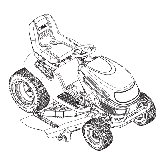
(Shown with optional bumper kit)
IMPORTANT: READ SAFETY
RULES AND INSTRUCTIONS
CAREFULLY
WHITE OUTDOOR, 60 OTTAWA STREET SOUTH, KITCHENER, ONTARIO N2G 3S7
772C0695
PRINTED IN THE UNITED-STATES
12/03
Advertisement

Subscribe to Our Youtube Channel
Related Manuals for White Outdoor GT-2550H


Summary of Contents for White Outdoor GT-2550H
- Page 1 PERATOR’S ANUAL Hydrostatic Garden Tractor Model: GT-2550H (Shown with optional bumper kit) IMPORTANT: READ SAFETY RULES AND INSTRUCTIONS CAREFULLY WHITE OUTDOOR, 60 OTTAWA STREET SOUTH, KITCHENER, ONTARIO N2G 3S7 772C0695 PRINTED IN THE UNITED-STATES 12/03...
- Page 2 XXXXXXXXXXX XXXXXXXXXX This is where your serial number will be. Copy the model number here: WHITE OUTDOOR CANADA Copy the serial number here: KITCHENER, ON N2G 4J1 CALLING CUSTOMER SUPPORT If you are having difficulty assembling this product or if you have any question regarding the controls, operation or maintenance of this unit, please call your service dealer.
- Page 3 SECTION 1: IMPORTANT SAFE OPERATION PRACTICES WARNING: This symbol points out important safety instructions which, if not followed, could endanger the personal safety and/or property of yourself and others. Read and follow all instructions in this manual before attempting to operate this machine. Failure to comply with these instructions may result in personal injury.
- Page 4 pasture) or piles of dry leaves. Dry grass or leaves DO NOT: may contact the engine exhaust and/or build up on 1. Do not turn on slopes unless necessary; then, turn the mower deck presenting a potential fire hazard. slowly and gradually downhill, if possible. 27.
- Page 5 Never allow children under 14 years old to k. To reduce fire hazards, keep machine free of operate the machine. Children 14 years old grass, leaves, or other debris build-up. Clean and over should read and understand the up oil or fuel spillage and remove any fuel operation instructions and safety rules in this soaked debris.
- Page 6 For safety protection, frequently check components 12. Do not change the engine governor settings or and replace immediately with original equipment over-speed the engine. The governor controls the manufacturer’s (O.E.M.) parts only, listed in this maximum safe operating speed of the engine. manual.
- Page 7 SECTION 4: SLOPE GAUGE...
- Page 8 SECTION 5: TRACTOR SET-UP NOTE: WARNING: Reference to RIGHT or LEFT side of the Do NOT operate the tractor tractor in this manual is observed from operator’s without first attaching both the steering position. wheel AND the seat. Doing so could result in serious injury to the operator.
- Page 9 IMPORTANT: case, free the seat from its shipping position and Your tractor is shipped with oil; remove the two hex screws (or knobs, on models so however, you MUST check the oil level before equipped) from the bottom of seat before proceeding operating.
- Page 10 ATTACHING THE CUTTING DECK 54” DECK Idler Pulley Left-Hand Deck Lift Assembly Idler Brkt. 3/8" Sq. Belt Guard Hole Notches Lift Cables Spring Deck Lift Arms Deck Idler Pulleys Fender Belt Guard Lift Lever PTO / Deck Belt Deck Support Pins Belt Guard Deck Roller Bracket Spindle Pulleys...
- Page 11 SECTION 6: KNOW YOUR GARDEN TRACTOR Compare the illustration in Figure 7 with the controls on your tractor; get familiar with these features before you start to operate the tractor. NOTE: Steering Wheel not shown for clarity. Figure 7 Systems Indicator Monitor/Hour Meter Ignition Switch PTO (Power Take-off) Knob Brake Pedal...
- Page 12 THROTTLE CONTROL LEVER Refer to STARTING THE ENGINE in the OPERATION section of this manual for detailed starting instructions. The throttle control lever is located on the right side of The ignition switch is also used to operate the the tractor’s dash panel. This lever controls the speed headlights.
- Page 13 CHOKE CONTROL PTO (POWER TAKE-OFF) LEVER The choke control can be found on the left side of the dash panel and is activated by pulling the knob outward. Activating the choke control closes the choke plate on the carburetor and aids The PTO lever is located on the left side of the in starting the engine.
- Page 14 PARKING BRAKE NOTE: The parking brake must be set if the operator BUTTON leaves the seat with the engine running or the engine will automatically shut off. To set the parking brake, fully depress the brake pedal and IMPORTANT: Always set the parking brake when push the parking brake button in.
- Page 15 Refer to the ADJUSTMENTS section of this manual WARNING: Do not leave the seat of the for more detailed instructions regarding various deck tractor without first placing the PTO knob (or adjustments. lever) in the disengaged (OFF) position, depressing the brake pedal and engaging the STARTING THE ENGINE parking brake.
- Page 16 IMPORTANT: • Watch for holes, ruts, bumps, rocks, or other hidden Never attempt to move the tractor objects. Uneven terrain could overturn manually without first engaging the hydrostatic relief machine. Tall grass can hide obstacles. valve. Doing so will result in serious damage to the •...
- Page 17 To turn the tractor’s headlights off: Carriage Screw • Turn the key either into the On position (to leave the engine running) or the Off position (to shut the engine off). Figure 9. WARNING: Never move the key into the Start position while the engine is running.
- Page 18 SECTION 8: MAKING ADJUSTMENTS Never attempt to make any WARNING: position) and rotate the blade nearest the discharge adjustments while the engine is running, chute so that it is parallel with the tractor. • Measure the distance from the front of the blade tip except where specified in the operator’s manual.
- Page 19 DECK ROLLER HEIGHT ADJUSTMENT Front tire toe-in can be measured as follows: To adjust the height of the rollers on the rear of the • Place the steering wheel in position for straight mowing deck, proceed as follows: ahead travel. •...
- Page 20 Standard Seat Brake Rod To adjust the position of the seat on models not equipped with a seat adjustment lever, loosen, but do NOT remove the four screws which secure the seat to the seat pivot bracket. Slide the seat forward or backward until desired position is reached.
- Page 21 SECTION 9: MAINTAINING YOUR GARDEN TRACTOR WARNING: 4. Attach the hose coupler to the water port on your Before performing decks surface. See Figure 21. maintenance or repairs, disengage PTO, move shift lever into neutral position, set parking 5. Turn the water on. brake, stop engine and remove key to prevent 6.
- Page 22 LUBRICATION Oil Fill Cap Protective Cap WARNING: Oil Drain Hose Before lubricating, repairing, or inspecting, always disengage PTO, move shift lever into neutral position, set parking brake, stop engine and remove key to prevent unintended starting. Engine Lubricate the engine with motor oil as instructed in the Engine Manual packed with your unit.
- Page 23 • Always keep the rubber boot positioned over the Hex Flange Nut positive terminal to prevent shorting. Wood Block IMPORTANT: If removing the battery for any reason, disconnect the NEGATIVE (Black) wire from it’s terminal first, followed by the POSITIVE (Red) wire. When re-installing the battery, always connect the POSITIVE (Red) wire its terminal first, followed by the NEGATIVE (Black) wire.
- Page 24 or a commercial battery cleaner. If necessary, scrape the battery terminals with a wire brush to remove Support Pin deposits. Coat terminals and exposed wiring with grease or petroleum jelly to prevent corrosion. CAUTION: Do not allow any cleaning solution to get inside the battery.
- Page 25 • Grasp the rearmost portion of the PTO idler bracket • Grasp the deck idler pulley and pivot it toward the and pivot it toward the discharge chute to relieve left side of the deck to relieve tension on the deck tension on the PTO belt.
- Page 26 Transmission Pulley (Beneath Cooling Fan) Fixed V-idler Pulley Left Frame Rail V-idler Pulley Flat idler Pulley Idler Extension Spring Engine Pulley Double-Idler Bracket Drive Belt FRONT OF TRACTOR Hydrostatic NOTE: Transmission View shown from above tractor. Figure 28 • Remove the drive belt by feeding it from front to •...
- Page 27 NOTE: NOTE: When storing any type of power equipment in Recharge the battery before returning it to an unventilated or metal storage shed, care should be service after storage. Even if the tractor starts, the taken to rustproof the equipment. Using a light oil or engine charging system may not bring the battery upto silicone, coat the equipment, especially any chains a full charge, unless it is recharged.
- Page 28 B&S OHV Single B&S OHV V-Twin (for throttle/pour la câble d'obturateur) (for choke/pour volet de départ) (deflector must face forward/ déflecteur doit faire face à l'avant) Tecumseh Twin Tecumseh Single (deflector must (deflector must face forward/ face forward/ déflecteur doit déflecteur doit faire face à...
- Page 29 REF. PART N°. DE N° DE RÉF. PIÈCE DESCRIPTION DESCRIPTION 710-0227 Hex Wash HD AB S-Tapp Scr #8 x .50 Vis taraudée no 8 x 0,50 710-0599 Hex Wash S-Tapp Scr 1/4-20 x .50 Vis autotaraudeuse à rondelle hex. de 1/4-20 x 0,5 710-0726 Hex Wash HD AB Tap Scr 5/16-12 x .75 Vis taraudée 5/16-12 x 0,75...
- Page 31 REF. PART N°. DE N° DE RÉF. PIÈCE DESCRIPTION DESCRIPTION 710-3015 Hex Cap Bolt 1/4-20 x .75" Lg. Gr. 5 Boulon 1/4-20 x 0,75 po de lg. Qual. 5 712-0324 Hex Ins. Locknut 1/4-20 Gr. 8 Nylon Écrou de blocage 1/4-20 Qual. 8 nylon 710-0895 Hex Tapp Scr 1/4-15 x .75"...
- Page 32 Models w/Manually Adjusting Seat Modèles avec siège à réglage manuelle Models w/Quick-Adjust seat Modèles avec siège à réglage facile...
- Page 33 REF. PART N°. DE N° DE RÉF. PIÈCE DESCRIPTION DESCRIPTION 747-1130B Deck Stabilizer Rod Tige de stabilisation du plateau de coupe 683-04079 Lift Shaft Assembly Arbre de relevage 683-04118 Lift Shaft Assembly 54" Deck Arbre de relevage, plateau de coupe de 54 po 711-0332 Clevis Pin Axe de chappe...
- Page 34 Torque to 400-480 IN-LB/ Serrez à un couple de 400 - 480 po - lb Torque to 130-230 IN-LB/ Serrez à un couple de 130 - 230 po - lb Torque to 400-480 IN-LB/ Serrez à un couple de 400 - 480 po - lb *with/avec 719-0399B *11/28...
- Page 35 REF. PART N°. DE N° DE RÉF. PIÈCE DESCRIPTION DESCRIPTION 683-0304C Lower Frame Assembly Châssis inférieur 683-04099 Lower Frame Assembly Châssis inférieur 783-0726B RH Pivot Support Bracket Support de pivot droit 783-0727A LH Pivot Support Bracket Support de pivot gauche 783-0728 Pivot Bar Bracket Support de la barre de pivotement...
- Page 36 41 60...
- Page 37 REF. PART N°. DE N° DE RÉF. PIÈCE DESCRIPTION DESCRIPTION 712-3050 Lub Nut, 7/16-14 Écrou, 7/16-14 629-0949A Reverse Wire Harness Adapter & Ground Adaptateur, fil de faisceau 783-04442 Double Idler Bracket Support de la poulie de tension double 710-0176 Hex Scr 5/16-18 x 2.75 Vis à...
- Page 38 Ground Wire Ref. Only./ Fil masse seulement comme référence.
- Page 39 REF. PART N°. DE N° DE RÉF. PIÈCE DESCRIPTION DESCRIPTION 783-0653F Steering Support Bracket Support de direction 717-1774A Electric PTO Clutch (54" Deck) Embrayage de la p.d.f électrique (54 po) 683-0618 Electric Clutch Anti-Rotation Bracket Support anti-rotatif de l'embrayage électrique 710-0859 Hex Cap Screw, 3/8-16 x 2.5 Vis à...
- Page 40 54-inch Deck Plateau de coupe 54 po Torque 710-1260A to 200-300 IN-LB/ Serrez 710-1260A à un couple de 200 - 300 po - lb Torque 712-3022 to 450-600 IN-LB/ Serrez 712-3022 à un couple de 450 - 600 po - lb Torque to 70-90 FT-LB/ Serrez à...
- Page 41 REF. PART N°. DE N° DE RÉF. PIÈCE DESCRIPTION DESCRIPTION 12650 Height Adjuster Réglage de hauteur 16606 Retainer Hook Brkt. Support du crochet de retenue 618-0671 Spindle Assembly 5.39 Dia. x .5625 Fusée, 5,39 dia. x 0,5625 683-0254 Deck Adjustment Brack w/Weld Nut Supp.
- Page 42 Electrical System Système électrique 18/19 783-0715A REF ONLY/ 783-0715A REF ONLY/ COMME R COMME RÉFÉRENCE SEULEMENT RENCE SEULEMENT Electric PTO harness shown. Manual PTO harness will vary slightly. Faisceau de fils à prise de force électrique. Faisceau de fils à prise de force manuelle varie un peut. REF.
- Page 43 THREE (3) YEAR LIMITED WARRANTY For three (3) years from the date of original purchase of our products, we will either repair or replace, at its option, free of charge, F.O.B. Factory or authorized service firm, any part found to be DEFECTIVE IN MATERIAL and WORKMANSHIP for the original purchaser.
- Page 44 NOTES...
Need help?
Do you have a question about the GT-2550H and is the answer not in the manual?
Questions and answers