Table of Contents
Advertisement
Quick Links
O
M
PERATOR'S
ANUAL
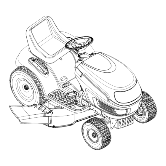
Hydrostatic Garden Tractor
Models GT-2150
GT-2550
IMPORTANT: READ SAFETY RULES AND INSTRUCTIONS CAREFULLY
Warning:
This unit is equipped with an internal combustion engine and should not be used on or near any unimproved forest-
covered, brush-covered or grass-covered land unless the engine's exhaust system is equipped with a spark arrester meeting
applicable local or state laws (if any). If a spark arrester is used, it should be maintained in effective working order by the operator.
In the State of California the above is required by law (Section 4442 of the California Public Resources Code). Other states may have
similar laws. Federal laws apply on federal lands. A spark arrester for the muffler is available through your nearest engine authorized
service dealer or contact the service department, P.O. Box 361131 Cleveland, Ohio 44136-9722.
WHITE OUTDOOR PRODUCTS COMPANY P.O. BOX 361131 CLEVELAND, OHIO 44136-9722
PRINTED IN U.S.A.
FORM NO. 770-10315
(11/99)
Advertisement
Table of Contents

Related Manuals for White Outdoor GT-2150


Summary of Contents for White Outdoor GT-2150
- Page 1 Federal laws apply on federal lands. A spark arrester for the muffler is available through your nearest engine authorized service dealer or contact the service department, P.O. Box 361131 Cleveland, Ohio 44136-9722. WHITE OUTDOOR PRODUCTS COMPANY P.O. BOX 361131 CLEVELAND, OHIO 44136-9722 PRINTED IN U.S.A.
-
Page 2: Table Of Contents
1-800-949-4483 Before calling your local White Outdoor dealer, make sure that you have your model and serial numbers ready. By having the model and serial numbers ready, you help your dealer give you faster service. To find your unit’s model and serial number, see SECTION 2: FINDING YOUR MODEL NUMBER. -
Page 3: Important Safe Operation Practices
SECTION 4: IMPORTANT SAFE OPERATION PRACTICES WARNING: THIS SYMBOL POINTS OUT IMPORTANT SAFETY INSTRUCTIONS WHICH, IF NOT FOLLOWED, COULD ENDANGER THE PERSONAL SAFETY AND/OR PROPERTY OF YOURSELF AND OTHERS. READ AND FOLLOW ALL INSTRUCTIONS IN THIS MANUAL BEFORE ATTEMPTING TO OPERATE YOUR LAWN MOWER. FAILURE TO COMPLY WITH THESE INSTRUCTIONS MAY RESULT IN PERSONAL INJURY. - Page 4 • Disengage all attachment clutches, thoroughly 3. CHILDREN depress the brake pedal, and take your foot off of Tragic accidents can occur if the operator is not alert to the the drive pedal before attempting to start engine. presence of children. Children are often attracted to the •...
- Page 5 • Keep all nuts, bolts and screws tight to be sure the • Do not change the engine governor settings or equipment is in safe working condition. overspeed the engine. Excessive engine speeds are dangerous. • Never tamper with safety devices. Check their proper operation regularly.
-
Page 6: Slope Gauge
Slope Gauge... - Page 7 SECTION 5: ATTACHMENTS & ACCESSORIES MODEL NUMBER DESCRIPTION OEM-190-118 Mulch Kit (For 46-inch Decks Only) OEM-190-603 Grille Guard Front Bumber Kit (Mounts On Front Of Tractor) ™ OEM-190-604 YardMate Storage Container (Mounts On Rear Of Tractor) ™ OEM-190-821 FastAttach Triple Bagger Grass Collector (For 46-inch Decks Only) ™...
- Page 8 ATTACHING THE CUTTING DECK (Units Equipped with a 50-inch Deck) Notches Deck Lift Assembly Lift Cables Deck Lift Arms Lift Lever PTO Idler Pulley Idler Spring PTO Belt Fender Electric PTO Clutch Deck Support Pins Deck Deck Skid Rod Stabilizer Bracket Discharge Chute Front of Tractor...
-
Page 9: Controls
SECTION 7: CONTROLS NOTE: Steering Wheel not shown for clarity. Figure 4 Ignition Switch G Drive Pedal Throttle Control Lever Brake Pedal Choke Control (if so equipped) Parking Brake Button Indicator Monitor/Hour Meter Cruise Control Button Lift Lever Seat Adjustment Lever PTO (Power Take-Off) Knob Cup Holder NOTE:... - Page 10 IGNITION SWITCH CHOKE CONTROL To start the engine, insert key into the ignition switch The choke control can be and turn clockwise to the START position. Release found on the left side of the key to the ON position once engine has fired. See dash panel and is activated by Figure 5.
- Page 11 DRIVE PEDAL PARKING BRAKE BUTTON To set the parking brake, fully depress the brake pedal and push the parking brake button in. Hold the button in while taking your foot off the brake pedal. Both the parking button and brake pedal will then...
-
Page 12: Operation
SECTION 8: OPERATION SAFETY INTERLOCK SWITCHES SETTING THE CUTTING HEIGHT This tractor is equipped with a safety interlock Select the height position of the cutting deck by system for the protection of the operator. If the placing the deck lift lever in any of the six different interlock system should ever malfunction, do not cutting height notches on the right side of the fender. - Page 13 STOPPING THE ENGINE SETTING THE CRUISE CONTROL • Place the PTO knob in the disengaged (OFF) NOTE: The cruise control feature should only be position utilized for travel in the forward direction. • Move the throttle control into the SLOW •...
- Page 14 MOWING position for the most efficient use of the cutting deck and other attachments. This tractor is equipped with one of White Outdoor’s high quality cutting decks. The following information • The operator must remain in the tractor seat will be helpful when using the cutting deck with your at all times.
-
Page 15: Adjustments
WARNING • Mowing should always be done with the To avoid possible injury, do engine at full throttle. not allow anyone in the area of the tractor while mowing. Small objects may be • Do not mow at high ground speed, especially picked up and discharged by the mower. - Page 16 Plate Gear Refer to separate engine manual packed with your unit for carburetor adjustment information or see Insert Dowel Here your White Outdoor dealer. Steering STEERING ADJUSTMENT Shaft NOTE: View shown from beneath tractor. If the tractor turns tighter in one direction than the...
-
Page 17: Maintenance
• With the tractor parked on a firm, level Side to Side surface, place the lift lever in the top notch If the cutting deck appears to be mowing unevenly, a (highest position) and rotate the blade nearest side to side adjustment can be performed. Adjust if the discharge chute so that it is parallel with necessary as follows: the tractor. - Page 18 CUTTING DECK REMOVAL Oil Fill Cap Protective Cap WARNING: Before performing Oil Drain Hose maintenance, move the PTO knob into the disengaged (OFF) position, engage the parking brake, turn the ignition key to the OFF position and remove the key from the switch Several attachments are available for your tractor.
- Page 19 Deck Lift Arms To Lift Assembly PTO Belt Deck Support Pins Deck Stabilizer Bracket PTO Idler Pulley Bracket Hooks Front of Tractor Electric PTO Clutch NOTE: Deck belt and other tractor Deck Stabilizer Rod components not shown for clarity. Figure 18 CHANGING THE DECK BELTS All belts on your tractor are subject to wear and should be replaced if any signs of cracking, shredding or rotting are present.
- Page 20 Proper removal of the drive belt requires the removal of several tractor components. Read through the following procedure prior to attempting it to determine if you feel you could successfully complete it. If you don’t, see your White Outdoor dealer to have the belt changed. IMPORTANT: Note the routing of the lower drive belt around all the pulleys and the belt keepers (if present) BEFORE performing the following steps.
- Page 21 Transmission Pulley (Beneath Cooling Fan) Fixed V-idler Pulley Left Frame Rail Flat Idler Pulley Electric PTO Clutch V-idler Pulley Idler Extension Spring Engine Pulley (Upper Portion) Double-Idler Bracket Drive Belt FRONT OF TRACTOR Hydrostatic Transmission NOTE: View shown from above tractor. Figure 20 •...
- Page 22 IMPORTANT: FUSE The fins on the cooling fan are only slightly flexible. Be careful not to damage the A fuse is installed in your tractor’s wiring harness to fan when removing the drive belt from around the protect the tractor’s electrical system from damage transmission pulley.
-
Page 23: Lubrication
IMPORTANT: It is extremely important that each cutting blade If the cutting edge of the blade has edge be ground equally to maintain proper blade already been sharpened to within 5/8" of the wind balance. An unbalanced blade will cause excessive wing radius, or if any metal separation is present, vibration when rotating at high speeds, may cause replace the blades with new ones. -
Page 24: Troubleshooting Guide
SECTION 12: TROUBLESHOOTING GUIDE Possible Trouble Corrective Action Cause(s) Engine will Safety switch There are three safety switches in the starting circuit of your unit: the brake pedal not crank button not switch, the seat switch and the PTO switch (units with manual PTO only). Make certain depressed. - Page 26 Models GT-2150 & GT-2550 17 20...
- Page 27 Tractor Body REF. PART DESCRIPTION 710-3015 Hex Cap Screw, 1/4-20 x .75 710-0599 Self-tapping Screw, 1/4-20 x .5 712-3006 Hex Nut, 1/4-20 710-0895 Self-tapping Screw, 1/4-15 x .75 710-0924 Pan Phillips Screw, 1/4-20 x .75 710-0528 Hex Cap Screw, 5/16-18 x 1.25 712-0292 U-type Speed Nut, 1/4-20 712-3004A...
- Page 28 Models GT-2150 & GT-2550...
- Page 29 Lift Assembly REF. PART REF. PART DESCRIPTION DESCRIPTION 747-1130 Deck Stabilizer Rod 710-0604A Self-tapping Screw, 5/16-18 x .625 683-0197 Lift Shaft Assembly 710-0895 Self-tapping Screw, 1/4-15 x .75 711-0332 Clevis Pin, .5 x .78 731-1990 Lift Lever Cover 712-0206 Hex Nut, 1/2-13 731-1993 Plastic Cover w/ Cup Holder 712-0431...
- Page 30 Models GT-2150 & GT-2550...
- Page 31 Steering Assembly REF. PART REF. PART DESCRIPTION DESCRIPTION 683-0304 Lower Frame Assembly 731-2296 Steering Wheel Insert 710-0604A Self-tapping Screw, 16-18 x .625 638-0017 LH Axle Assembly 783-0726A RH Pivot Support Bracket 638-0018 RH Axle Assembly 783-0727 LH Pivot Support Bracket 719-0525B Cast Iron Pivot Bar 783-0728...
- Page 32 Models GT-2150 & GT-2550 66 14...
- Page 33 Drive System REF. PART REF. PART DESCRIPTION DESCRIPTION 618-0379 Hydrostatic Transmission (Not Shown) 783-0782 Switch Actuator Bracket 629-0949 Reverse/Ground Wire Harness Adapter 647-0031 Brake Control Assembly 683-0251 Double Idler Bracket Assembly 647-0049 Drive Control Assembly 710-0189 Hex Cap Screw, 5/16-18 x 3.00 683-0267A Hydro Pedal Assembly 710-0216...
- Page 34 Models GT-2150 & GT-2550...
- Page 35 Power Take-off System REF. PART REF. PART DESCRIPTION DESCRIPTION 712-0431 Flange Lock Nut, 3/8-16 710-3180 Hex Cap Screw, 5/16-18 x 1.75 (Grade 5) 732-0735 Compression Spring, 1.318 x 2.37 732-0978 Extension Spring, 1.2 OD x 3.638 783-0733 Spacer Cup, 1.5 OD 710-0642 Self-tapping Screw, 1/4-20 x .750 732-0956...
- Page 36 Model GT-2150 46-inch Deck Model GT-2550 50-inch Deck...
- Page 37 Cutting Decks REF. PART REF. PART DESCRIPTION DESCRIPTION 17982 Reinforcement Spindle Plate 754-0474 Deck Belt 618-0430 Center Spindle Ass’y, 5 Dia. w/ Fitting 756-0627 Flat Idler Pulley, 3.5 OD 618-0431 Double Pulley Spindle Ass’y w/ Fitting 783-0139 Idler Bracket 683-0254 Deck Adjustment Bracket w/ Weld Nut 783-0141 Center Deck Skirt...
- Page 38 Models GT-2150 & GT-2550 18/19 REF. PART DESCRIPTION 625-0051 Bulb/Socket Headlight Assembly 629-0939 Wiring Harness w/o Ref. 14 629-0126 Harness Adapter, #18 x 5 710-0599 Self Tapping Screw, 1/4-20 x .5 712-3006 Hex Nut, 1/4-20 725-1426 Solenoid, 12-volt, 100 Amp...
- Page 39 Electrical System...
- Page 40 Models GT-2150 & GT-2550 (for choke) Briggs & Stratton Industrial Plus Twin (for throttle) (deflector must face forward) REF. PART DESCRIPTION 710-0148 Self-tapping Screw, #8-32 x .375 710-0599 Self-tapping Screw, 1/4-20 x .5 710-0604A Self-tapping Screw, 5/16-18 x .625 710-1237 Screw, #10-32 x .625...
- Page 41 Engine Accessories & Labels...
- Page 42 Notes...
- Page 43 Notes...
- Page 44 Products Co. with respect to new merchandise pur- d. White Outdoor Co. does not extend any warranty for chased and used in the United States, its possessions and products sold or exported outside of the United States territories.
Need help?
Do you have a question about the GT-2150 and is the answer not in the manual?
Questions and answers