Advertisement
Quick Links
Advertisement

Related Manuals for Pentax DSI-400 Series


Summary of Contents for Pentax DSI-400 Series
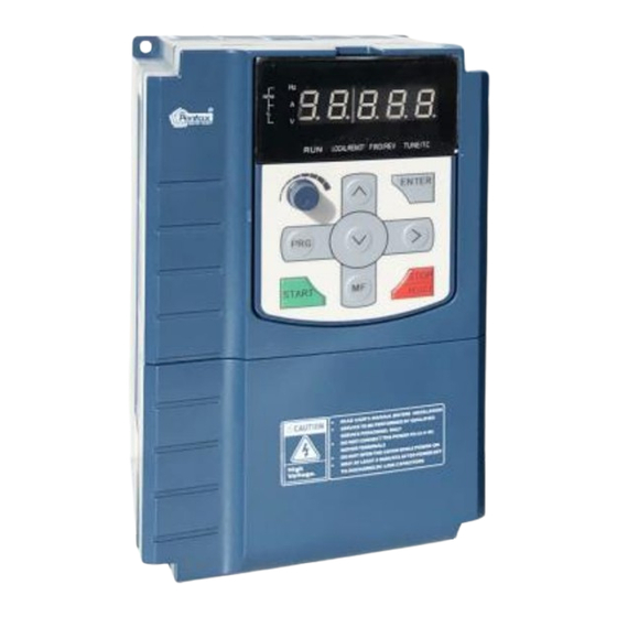
- Page 1 Pentax DSI-400 Series Frequency Inverter Users Manual...
- Page 2 Foreword Thank you for using the DSI-400 series of high-performance vector inverter. New DSI-400 series is a general current vector control inverter integrated with the performance and features in a high degree. DSI-400 with industry-leading drive performance and functionality control, using unique current vector control algorithm can efficiently drive induction motor to achieve high accuracy, high torque and high-performance control.
- Page 3 Definition of security In this manual, safety issues the following two categories: Warning: Due to the dangers posed against the required operation, may result in serious injury and even death; Caution: Due to the dangers posed against the required operation, may lead to moderate harm or minor injuries, and damage to the equipment;...
- Page 4 Safety precautions Before Installation Warning Do not install inverter finding the control system with water in, or inverter with missing parts or damaged parts. Please do not install inverter when the packing list is not consistent with the physical name. Warning Carefully handled when loading, otherwise it may damage the inverter.
- Page 5 damage to the inverter. Please install the inverter at the place of less direct sunlight and vibration. Please mind the location of its installation when more than two inverters are installed in one cabinet, so that radiation effect is promised. During Wiring Warning Operation shall be performed by the professional engineering technician.
- Page 6 Before Power-on: Caution Any part of the inverter need not to carry on pressure test,which has been done before leaving factory.Or accident may be caused. Please confirm whether the power voltage class is consistent with the rated voltage of the inverter and the Input terminal (R、S、T) and Output terminal(U、V、W)cable connecting positions are correct, and check whether the external circuit is short circuited and whether the connecting line is firm,otherwise it may damage the inverter.
- Page 7 of electric shock. At power-on, the inverter will perform the security check of the external strong-current circuit automatically. Thus, at this time please do not touch the terminals U、V、W, or the terminals of motor, otherwise there will be danger of electric shock. If the parameter identification is required, pay attention to the danger of injury arising from the rotating motor.
- Page 8 Make sure the inverter when the inverter voltage is lower than AC36V implementation of the maintenance and repair, five minutes after power prevail. Otherwise, the residual charge on the capacitor will cause damage! Make the inverter parameter settings, only with all pluggable plug in and out in the case of power outages!
- Page 9 ● Use with the voltage different with the rated voltage If the DSI-400 series inverter is used outside the allowable working voltage range as specified in this manual, it is easily lead to the inverter devices damage. If needed, use the corresponding boost or lower voltage transformer processing.
- Page 10 ●Change Three-phase Input to Two-phase Input It is not allowed to change the DSI-400 series three-phase inverter into two-phase. Otherwise, it may cause fault or damage to the inverter. This operation must be handed under HNC technical guidance.
- Page 11 3) Since the inverter has built-in standard parameters of the adaptable motors, it is necessary to perform motor parameter identification or modify the default values so as to comply with the actual values as much as possible, or it may affect the performance and protective properties. 4)Since short circuit cable or internal circuit of motor may cause alarm,or even machine explosion,please do insulation and short circuit test before the initial use as well as daily maintenance.Note:be sure to do this test, inverter and tested parts must be all separated!
- Page 12 EMC Guidance According to the national standard of GB/T12668.3, DSI-400 complys with the requirements for electromagnetic interference and anti-electromagnetic interference. DSI-400 series inverter meet international standard as below,the products have passed CE certification. : IEC/EN 61800-5-1 2003 Safety Regulationson Commissionable Electric Drive System :...
- Page 16 Nameplate specification Model specification Variable Frequency Inverter MODEL: DSI-400-1K5G3-00 POWER: 1.5KW INPUT: 3PH 400V~ 5.2A 50Hz/60Hz OUTPUT: 3PH 0-400V~ 3.7A 50HZ/60HZ Pentax Inverter DSI-400 – K75 G3-00 Inverter Series Voltage 220V Single-phase 0.75kW 380V Three-phase 1.5kW...
- Page 17 Section I. Product Information Though inverter hardware of GP unification is different, there are some optimization of software parameters for different load types . P type model is only suitable for pump, fan etc light load models, can not work at the rated current or more than the rated frequency for a long time.
- Page 18 Section I. Product Information DSI-400-045G3-00 96.4 DSI-400-055G3-00 117.6 DSI-400-075G3-00 166.4 DSI-400-093G3-00 184.3 DSI-400-110G3-00 226.8 DSI-400-132G3-00 268.1 DSI-400-160G3-00 321.1 DSI-400-187G3-00 368.0 DSI-400-200G3-00 406.6 DSI-400-220G3-00 442.7 DSI-400-250G3-00 503.0 DSI-400-280G3-00 555.9 DSI-400-315G3-00 650.7 DSI-400-355G3-00 734.5 DSI-400-400G3-00 787.6 DSI-400-450G3-00 846.0 DSI-400-500G3-00 885.0 Table 1-3 1.4 Product shape 1.4.1 Product Outline, Mounting Dimension, and Weight DSI-400−K40G1~DSI-400−2K2G1K, DSI-400−R75G3~ DSI-400-022G3/030P3 class...
- Page 19 Section I. Product Information DSI-400−030G3/037P3~DSI-400-090G3/110P3 class DSI-400−110G3/132P3~DSI-400-315G3/355P3 class DSI-400−355G3/400P3~DSI-400-500G3 class...
- Page 20 Section I. Product Information...
- Page 21 Section I. Product Information Fig.1−4 Product outline and mounting dimension Shape dimension(mm) Installation dimension(mm) Shape DIM Asse mbly aper DSI-400-K40G1 ture DSI-400-K75G1 DSI-400-1K5G1 DSI-400-2K2G1 DSI-400−K75G3 DSI-400-1K5G3 DSI-400-2K2G3 DSI-400-004G3 DSI-400-5K5G3 DSI-400-7K5G3/011P3 DSI-400-011G3/015P3 DSI-400-015G3/018P3 DSI-400-018G3/022P3 DSI-400-022G3/030P3 DSI-400-030G3/037P3 DSI-400-037G3/045P3 DSI-400-045G3/055P3 DSI-400-055G3/75P3 DSI-400-075G3/90P3 DSI-400-090G3/110P3 ——...
- Page 22 Section I. Product Information DSI-400-110G3/132P3 —— DSI-400-132G3/160P3 DSI-400-160G3/185P3 DSI-400−185G3/200P3 DSI-400−200G3/220P3 DSI-400−220G3/250P3 —— 1035 DSI-400−250G3/280P3 DSI-400−280G3/315P3 DSI-400−315G3/355P3 DSI-400−355G3/400P3 DSI-400−400G3/450P3 —— 1240 DSI-400−450G3 DSI-400−500G3...
- Page 23 Section I. Product Information 5 Standard specification Item Specifications High performance of current vector control technology to realize Control system asynchronous motor and synchronous motor control Drive performance High efficiency driving for induction motor and synchronous motor Maximum frequency Vector control:0~500Hz; V/F control:0~3200Hz 0.5k~16kHz;the carrier frequency will be automatically adjusted Carrier frequency according to the load characteristics...
- Page 24 Section I. Product Information Simple PLC and MS speed It can realize at maximum of 16 segments speed running via the built- running in PLC or control terminal. Built-in PID It is easy to realize process-controlled close loop control system Auto voltage regulation It can keep constant output voltage automatically in case of change of (AVR)
- Page 25 Section I. Product Information 0~20mA current input. Standard: 2 digital output terminals, FM is high-speed pulse output terminal (can be chosen as open circuit collector type), support 0~100kHz square wave signal; Output terminal 2 relay output terminal; 2 analog output terminals, support 0~20mA output current or 0~10V output voltage;...
- Page 26 Section II. Installation &Wiring 2.1 Use of the environment Ambient temperature-10℃~40℃. Avoid electromagnetic interference and keep the unit away from the source of interference. Prevent dropping water, steam, dust powder, cotton fiber or fine metal powder from invasion. Prevent oil, salt and corrosive gas from entering it. Avoid vibration.
- Page 27 Section II. Installation &Wiring Fig. 2-2.1 Heat dissipation problems should be concerned when doing mechanical installation, please mind rules belows: Mounting space is shown in 2-2.1, which could ensure the heat sinking space of the inverter. However, the heat sinking of other devices in the cabinet shall also be considered. Install the inverter vertically so that the heat may be expelled from the top.However, the equipment cannot be installed upside down.
- Page 28 Section II. Installation &Wiring 2.4 Wiring The wiring of frequency inverter includes two parts: main circuit and control circuit. Users must ensure correct connections according to the following connection diagram. 2.4.1 DSI-400 diagram 0.4kW-22kW 30kW-400kW Brake resistor Brake resistor Brake unit Breaker Three phase AC power supply...
- Page 29 Section II. Installation &Wiring Main circuit terminals (G type) 2.5.1 DSI-400 main circuit terminals Terminal Name Function description R、S、T Three phase power input terminal External Break resistor reserved P+、PB terminal(0.4KW~22KW) U、V、W Three phase AC output terminal Earth terminal 2.5.2 Caution of Main Circuit wiring 1)Input Power R、S、T:...
- Page 30 Section II. Installation &Wiring 2.6.2 Control circuit terminals description Terminals function description: Terminal Terminal Type FunctionDescription sign Name Provide +10V power supply for external units, with maximum output current of 10mA. +10V- External terminal of It is generally used as the operating power supply for 10V power supply the external potentiometer.
- Page 31 Section II. Installation &Wiring 1. Input impedance:2.4 kΩ. DI5-OP Digital Input 5 DI6-OP Digital Input 6 Same as DI1 DI7-OP Digital Input 7 Same as DI1 DI5 can be used as high-speed pulse input channel. High-speed pulse input terminal DI5-OP Maximum input frequency:100kHz.
- Page 32 Section II. Installation &Wiring 2.6.3 Description of wiring of control terminals 1) Analog input terminal Because the weak analog signal will be easily affected by the external interference, generally shielded cable shall be used, the cable length shall be as short as possible and no longer than 20 meters, as shown in Fig.
- Page 33 Section II. Installation &Wiring 2) Digital input terminal It needs to employ shielded cable generally, with wiring distance of no longer than 20 meters. When valid driving is adopted, necessary filtering measures shall be taken to prevent the interference to the power supply. It is recommended to use the contact control mode.
- Page 34 Section II. Installation &Wiring +24V +24V +VCC 3.3Ω 4.7K Signal 4.7K External controller Inverter control board Fig. 2-6.4 Source wiring mode This connection mode must make OP of jumper J9 connect to COM port,and connect +24V and public terminal of external controller together.If you use an external power supply,jumper J9 must be removed,and connect external negative power supply to OP ,while positive power supply to DI port.
- Page 35 Section II. Installation &Wiring 2.7 Standby circuit Inverter fault or jump may cause great breakdown loss or other accident. To avoid this happens, please add the standby circuit below to ensure security. Note:Confirm and test the running characteristic of the standby circuit, make sure that the industrial phase and the converter phase are in the same direction.
- Page 36 Section III. Fittings 3.1 Connection with peripheral devices 3.1.1 Connection of the Product and Peripheral Devices Input AC Power Supply Automatic Circuit Breaker Input Contactor Input AC Reactor Input EMC Filter DC Reactor Inverter Brake Resistor Earth Output EMC Filter Output AC Reactor 3 Phase motor Motor Earth...
- Page 37 CSA standard but existing equipment that anti- interference ability is not sufficient. If needing the filter, please connect with the company. Improve the power factor of the input side: DSI-400 series can adopt DC reactor external DC reactor 1.Improve the overall efficiency and thermal stability according to the need.
- Page 38 Section IV. Keyboard Operation harmonics at the input side on the inverter and reduce the external conduction and radiation interference. The inverter output side generally has higher harmonic.When the motor is far from the inverter, since there are many capacitors in the circuit, certain harmonics will cause resonance in the circuit and bring in the following results:...
- Page 39 Section IV. Keyboard Operation 3.2 Mounting hole dimension 3.2.1 Braking unit & Braking resistance When customers choose the type with braking,there will be braking unit inside the inverter, maximum braking torque is 50%.Please refer to the table below and choose the matched braking resistance separately.
- Page 40 HNC braking unit. External DC reactor installation: For DSI-400 series inverter, external DC reactor can be ordered according to your needs.When installation,you should tear down copper platoon between DC+1 and DC+2 of inverter main circuit.And then add reactor between DC+1 and DC+2,wiring between reactor terminals and inverter terminals DC+1 and DC+2 have no polarity.
- Page 41 Section IV. Keyboard Operation 3.2.2 Specifications of circuit breaker、cable and contactors Terminal screwPE R、S、T、 ⊕ 、B、 Ө 、U、V、W breaker contactor Shape DIM (A) Fastening Fastening (A) Wire Wire Terminal Terminal Moment Moment standard standard screw screw (N·m) (N·m) DSI-400−K40G1 1.2~1.5 1.2~1.5 DSI-400−K75G1 1.2~1.5...
- Page 42 Section IV. Keyboard Operation Section IV. Keyboard Operation 4.1 Keyboard size 4.1.1 DSI-400 keyboard specification RUN LOCAL/REMOT FWD/REV TUNE/TC Fig. 4-1.1 4.1.2 Keyboard warehouse JP3 dimension Fig. 4-1.2...
- Page 43 Section IV. Keyboard Operation 4.2 Display Interface Modification of function parameter, monitoring of inverter operation, control of inverter operation (start and stop) can be performed through the operation panel.Its shape and function area are shown as below: Fig. 4-2.1 4.2.1 Function description of operation panel Keyboard Parameter Description Forward/Reserved Running Light...
- Page 44 Section IV. Keyboard Operation Tuning/Fault indicator *ON:torque control mode TUNE/TC *Slow flashing:tuning state *Quick flashing:fault state Unit indicator * Hz frequency unit Hz A V *A current unit RPM(Hz+A) *V voltage unit %(A+V *RMP(Hz+A)revolving speed unit *%(A+V)percentage Digital display area Digital display *5-bit LED display,monitor set frequency,output frequency,various monitoring data,alarm code etc.
- Page 45 Section IV. Keyboard Operation Potentiometer Potentiometer * P0.03 is set to 4 as default; Running key * It is used to start the running of the inverter under keyboard control mode Stop/reset * In running status,it can stop the running by pressing this key. In alarm STOP/RESET status,it can reset operation with this key.
- Page 46 Section IV. Keyboard Operation 4.3 Examples for parameter setting 4.3.1 Description of function code viewing and modification method The operation panel of DSI-400 inverter adopts three-level menu structure to perform parameter setting.The three-level menu includes : function parameter group(level1menu)→ function code(level 2 menu)→setting value of function code(level 3 menu).The operation process is as shown in Figure below.
- Page 47 Section IV. Keyboard Operation Sequence display inverter function parameters ,there are Function parameter mode P0~PF、A0~AF、U0~UF function groups respectively. User set individual function parameters(32 at most), parameters User set parameter mode that needed to be displayed can be set through PE group User modify parameter mode Inconsistent with factory default parameters Table 4-3.1...
- Page 48 Section IV. Keyboard Operation Relevant function parameters PP.02、PP.03 set as below: Parameters display mode Default attributes value 1bit U group display selection No display PP.02 Display Set range 10bit A group display selection No display Display Individual parameter mode Default display selection value 1bit...
- Page 49 Section IV. Keyboard Operation Switching mode as below: E.g:To switch current function parameter mode to user set parameter mode. PRG+>>SHIFT ENTER Fig. 4-3.3 4.3.3 User set parameter operation mode User set menu is established for quick checkup and modification. The display mode is “uP3.02”,which represents function parameter P3.02.
- Page 50 4.3.6 Motor parameter automatic tuning Vector control running mode:before running, user must accurately input motor nameplate parameters. DSI-400 series inverter will be matching standard motor parameter according to this nameplate. Vector control methods are very much dependent on motor parameters, to get good control performance, accurate control motor parameters must be acquired.
- Page 51 Section IV. Keyboard Operation A3.04:Motor rated frequency A3.05:Motor rated revolving speed A4.00:Motor type selection A4.01:Motor rated power Motor 4 A4.02:Motor rated voltage A4.03:Motor rated current A4.04:Motor rated frequency A4.05:Motor rated revolving speed Table 4-3.4 E.g:Asynchronous motor parameter tuning If motor and the load can be totally separated, please select P1.37(Motor 2\3\4 as A2\A3\A4.37) to 2(Asynchronous machine complete tuning), then press RUN key on keyboard panel, inverter will automatically calculate the motor of the following parameters:...
- Page 52 Section IV. Keyboard Operation A3.07: Asynchronous motor rotor resistance A3.08: Asynchronous motor leakage inductance A3.09: Asynchronous motor mutual inductance P3.10: Asynchronous motor no-load current A4.06: Asynchronous motor stator resistance A4.07: Asynchronous motor rotor resistance Motor 4 A4.08: Asynchronous motor leakage inductance A4.09:...
- Page 53 Section V. Parameter Function Table Caution: The symbols in the function table are explained as follows: “★”:indicates that the parameter setup value cannot be modified when the inverter is in the running status. “●”:indicates that the parameter value is the actual detection record and cannot be modified. “☆”:indicates that the parameter setup value can be modified when the inverter is in stop status and running status.
- Page 54 Section V. Parameter Function Table U0.01 Setting frequency(Hz) 0.01Hz Inverter current actual output frequency U0.02 DC bus voltage(V) 0.1V Detection value of DC bus voltage U0.03 The output voltage(V) Inverteractual output voltage U0.04 Motor output current(A) 0.01A Valid value of motor actual current U0.05 The output power(kW) 0.1kW...
- Page 55 Section V. Parameter Function Table IO output status,it’s value is a hexadecimal digit.Each bit corresponds to each output terminal state : 0~9 bit Output status Invalid Valid VDO5 TA1-TB1-TC1 VDO4 VDO3 TA2-TB2-TC2 VDO2 VDO1 U0.09 AI1 voltage(V) 0.01V AI1 input voltage, corrected by AC.00~AC.03 U0.10 AI2 voltage(V) 0.01V...
- Page 56 Section V. Parameter Function Table PID percentage of feedback value for running adjustment. U0.17 PLC stage PLC program running stage-display U0.18 PULSE pulse input frequency(kHz) 0.01kHz Display PULSE pulse input frequency,unit 0.01Khz U0.19 Speed feedback(Unit 0.1Hz) 0.1Hz synchronous speed,accurate to 0.1hz U0.20 Surplus running time 0.1Min...
- Page 57 Section V. Parameter Function Table PG feedback speed, accurate to 0.1hz U0.30 Main frequency X display 0.01Hz P0.03 main frequency source set frequency U0.31 Auxiliary frequency Y display 0.01Hz P0.04 auxiliary frequency source set frequency U0.32 View arbitrary memory address value To view arbitrary memory address, advanced commissioning function.
- Page 58 Section V. Parameter Function Table Display DI input status intuitively, offer DI input information more detailed than U0.07, advanced display function. U0.42 DO output status intuitive display Display DO output status intuitively, offer DO output information more detailed than U0.08, advanced display function.
- Page 59 Section V. Parameter Function Table -100.00%~100.00% U0.60 Running frequency(%) 0.01% -100.00%~100.00% U0.61 Inverter status U0.62 Current fault code U0.63 Point to point communication 0.01% U0.64 From the number of stations U0.64 Torque limit 0.01% 5-2 Basic function group:P0.00-P0.28 Factory Change Code Description/Display Setting Range...
- Page 60 FVC is generally used for permanent magnet synchronous motor, while part of the small power applications can select V/F control mode. DSI-400 series support specific models of permanent magnet synchronous motor sensorless vector control mode. Please refer to DSI-400 users manual and DSI-400S dedicated users manual for using method.
- Page 61 3:AI2 4:AI3(Potentiometer) Frequency is determined by analog input terminal. DSI-400 series control board offers 2 analog input terminal(AI1,AI2), optional device TZ5PC1 card can offer 1 isolated analog input terminal(AI3x). AI1,AI2 can be chosen as 0V~10V voltage input as well as 0mA~20mA current input by the jumper...
- Page 62 MS command running mode is set through different combination mode of digital input DI terminal. There are 4 MS command terminals with 16 status of DSI-400 series. PC group function codes correspond to 16 “MS command”. “MS command” is percentage relative to P0.10( maximum frequency).
- Page 63 Section V. Parameter Function Table AI3(Potentiometer) PULSE setup (Dl5) MS command Simple PLC PID setup Communication setup When the auxiliary frequency source is used as independent frequency reference channel (i.e. frequency source switching from X to Y), it is used in the same way as the relative specifications of P0.03. When the auxiliary frequency source is used as overlap reference (i.e.
- Page 64 Section V. Parameter Function Table Switching between X & Y Switching between X & option 1 Switching between Y & option 1 Relationship between main /auxiliary 10bit frequency source Main+auxiliary Main-auxiliary MAX (main frequency source X, auxiliary frequency source Y) MIN (main frequency source X, auxiliary frequency source Y) This parameter is used to select frequency setup channel, and of realizing frequency setup through the...
- Page 65 Section V. Parameter Function Table 2: MAX (main frequency source X, auxiliary frequency source Y) Choose bigger absolute value of the two as target frequency 3: MIN (main frequency source X, auxiliary frequency source Y) Choose smaller absolute value of the two as target frequency. Besides, when frequency source is main&...
- Page 66 Section V. Parameter Function Table Communication setup It defines the source of frequency upper limit. Frequency upper limit comes from digital setup (P0.12) or analog input channel. When upper limit is set through analog input, 100% of analog input corresponds to P0.12.
- Page 67 Section V. Parameter Function Table Different power of inverter is set with different carrier frequency by the factory. Though user could modify it , attention should be paid:if carrier frequency is set higher than the factory set valule, it will lead to inverter radiator temperature rise increasing.
- Page 68 Section V. Parameter Function Table GROUP 4:P8.07、P8.08. 1second ★ P0.19 0.1 seconds Acc./dec. time unit 0.01 seconds DSI-400 offers 3 kinds of speed-up /speed down time unit to meet the need of all kinds of scene.Respectively for 1 second、0.1 seconds and 0.01 seconds. Caution:Decimal places as well as corresponding acceleration/deceleration time of the 4 groups may be changed when modifying this function parameter,special attention should be paid in the process of application.
- Page 69 Section V. Parameter Function Table nameplate parameters, independent parameter tuning, control mode, parameters relating to operation performance respectively. Motor 1 corresponding function groups are P1 group and P2 group. Motor 2,motor 3, motor 4 corresponding groups are A2 group, A3 group and A4 group respectively. Users select current motor through P0.24 function code as well as digital input terminal DI.
- Page 70 Section V. Parameter Function Table Communication setup Terminal command bound frequency 10bit source selection Without bound Digital setup frequency source AI3(Potentiometer) PULSE pulse setup(DI5) MS command Simple PLC Communication setup Communication command binding 100bit frequency source selection Without bound Digital setup frequency source AI3(Potentiometer) PULSE pulse setup(DI5) MS command...
- Page 71 Profibus.DP communication card DSI-400 series offers 3 kinds of communication mode. All of the 3 need to be equipped with optional communication card .And they can not be used at the same time. P0.28 is used to set the type of the optional communication card. When user replace the communication card , P0.28 should be properly set.
- Page 72 Section V. Parameter Function Table leakage inductance 0.001mH~65.535mH(Inverter power >55kW) 0.1mH~6553.5mH(Inverter power <=55kW) Asynchronous motor mutual ★ P1.09 inductance 0.01mH~655.35mH(Inverter power >55kW) 0.01A~P1.03(Inverter power <=55kW) Asynchronous motor no ★ P1.10 load current 0.1A~P1.03(Inverter power >55kW) P1.06~P1.10 are parameters for asynchronous motor.Generally, motor nameplate dosen’t contain such parameters, users can get them throng inverter auto tuning.
- Page 73 Section V. Parameter Function Table ★ P1.34 1~65535 Rotary transformer pole pairs Rotary transformer is equipped with pole pairs.When using the encoder, correct parameters must be set to it. ★ P1.36 PG dropped inspection time 0.0s 0.0s:no action 0.1s~10.0s It is used to set inspection time of encoder disconnection fault.When feedback signal is 0.0s, encoder disconnection fault will not be inspected.
- Page 74 Section V. Parameter Function Table It is used for no encoder 5-4 Vector control function group:P2.00-P2.23 P2 group function codes are valid for vector control and invalid for V/F control. Factory Change Code Description/Display Setting Range Setting Limite ☆ P2.00 Speed loop proportional gain1 1~100 ☆...
- Page 75 Section V. Parameter Function Table during overshoot drop. ☆ P2.06 100% Vector control slip gain 50%~200% This parameter is used to adjust motor steady speed precision for zero-speed sensor vector control mode. Please turn up the parameter value when with load motor running in low speed. On the contrary, when the with load motor running in high speed, please turn down the parameter value.
- Page 76 Section V. Parameter Function Table P2.10 AI3(Potentiometer) Torque upper limit source in ☆ speed control mode P2.11 PULSE setup (regenerative) Communication setup Min(AI1,AI2) Max(AI1,AI2) Torque upper limit digital setup 0.0%~200.0% ☆ P2.12 150.0% in speed control mode (regenerative) 0~20000 Excitation regulation ☆...
- Page 77 Section V. Parameter Function Table Disable Regenerative power limit ☆ P2.22 selection enable Mode 0.0~200.0% ☆ P2.23 Regenerative power limit dependent 5-5 V/F control group:P3.00-P3.26 This function group is only valid for V/F control mode. V/F control is suitable for general load such as draught fan, pump. It is also appropriate for situations where one inverter driving multiple motors or there is big difference between inverter power and motor power.
- Page 78 Section V. Parameter Function Table The relationship between V&F is connected with P1 group(motor rated voltage and rated frequency). Suppose that voltage source input is X (X from 0~100%), the V,F relationship is: V/F=2*X*(Motor rated voltage)/(Motor rated frequency) ★ P3.01 0.0%~30% Torque boost value Torque boost cut-off frequency...
- Page 79 Section V. Parameter Function Table P3.05~Motor rated frequency(P1.04)No te:Motor Multi-point V/F frequency ★ P3.07 0.00Hz 2\3\4 rated frequency respectively point F3 A2.04\A3.04\A4.04 Multi-point V/F voltage point ★ P3.08 0.0% 0.0%~100.0% Six parameters of P3.03 to P3.08 define the multi-point V/F curve. The setup value of multi-point V/F curve is generally set in accordance with the load characteristics of the motor.
- Page 80 Section V. Parameter Function Table voltage protection limitation value. The higher the over excitation gain is, more powerfully the suppression effect is. The setting is described as follows: In the applications where over-voltage alarm easily occurs, it needs to improve the over-excitation gain. Excessive over-excitation gain easily lead to increasing of output current .Users should keep the balance during operation.
- Page 81 Section V. Parameter Function Table 0:Digital setup(P3.14) Voltage is directly set through P3.14. 1: AI1 2: AI2 3:AI3(Potentiometer) Voltage is set through analog input terminal. 4: PULSE pulse setup(DI5) voltage set through terminal pulse. Pulse setup signal specification:voltage range 9V~30V, frequency range 0kHz~100kHz. 5:...
- Page 82 DSI-400 series inverter has 7 multifunctional digital input terminals (DI1 to DI7), of which DI5 can be used as high-speed pulse input terminal, and DSI-400 series inverter also has 2 analog input terminals.If system needs more input/output terminal, it can be equipped with multi-function input/output expansion card and 1 analog input terminal(AI3x).
- Page 83 Section V. Parameter Function Table Factory Change Code Description/Display Setting Range Setting Limite ★ P4.00 DI1terminal function selection 0~59 ★ P4.01 DI2 terminal function selection 0~59 ★ P4.02 DI3 terminal function selection 0~59 ★ P4.03 DI4 terminal function selection 0~59 ★...
- Page 84 Section V. Parameter Function Table Inverter decelerates to stop, but all operation parameters are memorized. E.g : PLC parameter, swing frequency Operation suspended parameter, PID parameter. When this terminal signal disappeared, inverter restored to running status as before. When the inverter detects that the signal occurs , it will report “15=Err15”...
- Page 85 Section V. Parameter Function Table restores to the initial status of PLC running. When this terminal command is valid, the inverter maintains the frequency output of the swing frequency center, and the Swing frequency pause swing frequency pauses. It is used as input terminal of the counting pulse. Counter input When this terminal command is valid, it clears the counting Counter reset...
- Page 86 Section V. Parameter Function Table Motor selection terminal1 It can realize 4 groups of motor parameters switching by 4 combination status of this 2 terminals.For details please Motor selection terminal2 refer to schedule3. PA.18=1, the parameter is invalid, PID parameter takes PID parameter switching use of PA.05~PA.07.
- Page 87 Section V. Parameter Function Table PC.01 MS command 1 PC.02 MS command 2 PC.03 MS command 3 PC.04 MS command 4 PC.05 MS command 5 PC.06 MS command 6 PC.07 MS command 7 PC.08 MS command 8 PC.09 MS command 9 PC.10 MS command 10 PC.11...
- Page 88 Section V. Parameter Function Table Corresponding Terminal2 Terminal1 Acc./dec. selection parameter P1、P2 group Motor 1 A2 group Motor 2 A3 group Motor 3 A4 group Motor 4 P4.10 DI filter time 0.000s~1.000s ☆ 0.010s If the digital input terminal malfunction because it is vulnerable to interference , users could increase the parameter value to enhance the interference immunity.
- Page 89 Section V. Parameter Function Table 0:Two-line mode 1: This mode is the most commonly used forward/Reserved rotation control mode. The forward/Reserved rotation of the motor is decided by the Di1, DI2 terminal commands. The descriptions on the terminal running command are as shown as below: Terminal Set value Description...
- Page 90 Section V. Parameter Function Table Fig. 5-6 Two-line control mode 1 1: Two-line mode 2: In this operation mode,DI1 terminal function is to enable operation,while DI2 terminal function is to determine running direction. The descriptions on the terminal running command are as shown as below: Terminal Set value Description...
- Page 91 Section V. Parameter Function Table Fig. 5-7 Two-line control mode 2 2:Three-line mode1 In this operation mode, DI3 terminal is the enable terminal, running direction controlled by DI1terminal 、 DI2terminal. The descriptions on the terminal running command are as shown as below: Terminal Set value Description...
- Page 92 Section V. Parameter Function Table Fig. 5-8 Three-line control mode 1 Among them: SB1:Stop button SB2:Forward rotation button SB3:Reserved rotation button 3:Three-line mode2 In this operation mode, DI3 terminal is the enable terminal, Direction by the state of the DI2 to decide,while DI1 terminal function is to determine running direction.
- Page 93 Section V. Parameter Function Table Fig. 5-9 Three-line control mode 2 Among them : SB1:Stop button SB2:Running button 4:Two-line mode3 this operation mode is Priority control two-line mode.The forward/Reserved rotation of the motor is decidedby the Di1, DI2 terminal commands. The descriptions on the terminal running command are as shown as below:...
- Page 94 Section V. Parameter Function Table 0->1 Reserved(REV) 5:Three-line mode3 In this operation mode, DI3 terminal is the enable terminal, running direction controlled by DI1terminal 、 DI2terminal. The descriptions on the terminal running command are as shown as below: Terminal Set value Description Forward(FWD) Reserved(REV)
- Page 95 Section V. Parameter Function Table Fig. 5-8 Three-line control mode 1 Among them: SB1:Stop button SB2:Forward rotation button SB3:Reserved rotation button Terminal UP/DOWN variation ☆ P4.12 0.01Hz/s~65.535Hz/s 1.00Hz/s rate It is used to set the frequency variation rate (frequency variation per second) when adjusting the set frequency with terminals UP/DOWN.
- Page 96 Section V. Parameter Function Table Corresponding setting ( frequency , torque ) 100% 0V(0mA) 10V(20mA) -100% Fig. 5-10 Relationship between analog input and setup value The parameters mentioned above define the relationship between analog input voltage and the analog input setup value. When analog input voltage exceeds the setup “maximum input”...
- Page 97 Section V. Parameter Function Table AI curve 2 maximum input ☆ P4.21 100.0% -100.00%~100.0% corresponding setup ☆ P4.22 0.10s AI2 filter time 0.00s~10.00s For function and usage of curve 2, please refer to description of curve 1. ☆ P4.23 -10V AI curve 3 minimum input -10.00V~P4.25 AI curve 3 minimum input...
- Page 98 Section V. Parameter Function Table Curve3(2 points,see P4.23~P4.26) Curve4(4 points,see A6.00~A6.07) Curve5(4 points,see A6.00~A6.07) 100bit AI3 curve selection Curve1(2 points,see P4.13~P4.16) Curve2(2 points,see P4.18~P4.21) Curve3(2 points,see P4.23~P4.26) Curve4(4 points,see A6.00~A6.07) Curve5(4 points,see A6.00~A6.07) The 1bit, 10bit, 100bit of the function code are used to choose the set curve of analog input AI1、AI2、 AI3 respectively.
- Page 99 Section V. Parameter Function Table below the setup of minimum input. The 1bit, 10bit, 100bit of the function code are corresponding to the analog input AI1 、AI2、AI3 respectively. If the bit is set to 0 and AI is below the minimum setup , the analog input setup is the curve “minimum input corresponding setup”(P4.14、P4.19、P4.24) .
- Page 100 Low level valid:Connection between COM and corresponding DI is invalid,disconnection valid. 5-7 Output terminal:P5.00-P5.22 DSI-400 series inverter provides two multifunctional analog terminal output selections,two multifunctional relay output terminal, two DO terminal (FM can be used as high speed pulse output terminal as well as open collector switching output).
- Page 101 Section V. Parameter Function Table When P5.00 is set to 0, maximum output frequency can reach 10kHz , please refer to P5.06 for related description. FMRselection (open 0-41 ☆ P5.01 collector output terminal) Relay output selection 0-41 ☆ P5.02 (TA1.TB1.TC1) Relay output selection 0-41 ☆...
- Page 102 Section V. Parameter Function Table When the counting value reaches the value of PB.08, it Setup counting value arrived outputs ON signal. When the counting value reaches the value of PB.09, it Designated counting value arrived outputs ON signal.Refers to PB group for details. When the actual length exceeds the setup value in Length arrived PB.05, it outputs ON signal.
- Page 103 Section V. Parameter Function Table P8.16 set value, it outputs ON signal. Inspection level of FDT2 frequency Please refer to function code P8.28、P8.29 for details. Frequency 1 arrival output Please refer to function code P8.30、P8.31 for details. Frequency 2 arrival output Please refer to function code P8.32、P8.33 for details.
- Page 104 Section V. Parameter Function Table terminal) ☆ P5.07 AO1 output function selection 0-16 ☆ P5.08 AO2 output function selection 0-16 FMP terminal output pulse frequency range:0.01kHz~P5.09(FMP maximum frequency output), P5.09 could vary from 0.01kHz to 100.00kHz. AO1, AO2 output ranges from 0V to 10V, or 0mA to 20mA. The corresponding value range is shown in the table below:...
- Page 105 Section V. Parameter Function Table When the multifunctional terminal output function selects FMP pulse output, it can set the maximum frequency value of output pulse. ☆ P5.10 AO1 zero offset -100.0%~+100.0% 0.0% ☆ P5.11 AO1 gain -10.00~+10.00 1.00 Expansion card AO2zero ☆...
- Page 106 Section V. Parameter Function Table Positive logic Negative logic 1000 DO1 terminal valid state setup Positive logic Negative logic 10000 DO2 terminal valid state setup Positive logic Negative logic Define output terminal FMR、Relay 1、Relay 2、DO1 andDO2 output logic. 0: Positive logic Digital output terminals and the corresponding public end connected as effective state, disconnect for invalid state.
- Page 107 Section V. Parameter Function Table 0: Direct startup: When the DC brake time is zero, it starts at the startup frequency. When the DC brake time is non-zero value, it can perform DC brake before start. It is suitable for the applications where small inertia may cause Reserved rotation at the time of startup.
- Page 108 Section V. Parameter Function Table 0.0s~100.0s ★ P6.04 0.0s Start frequency holding time To ensure the torque at the time of startup, proper startup frequency shall be set. In addition, in order to set up magnetic flux when waiting for the startup of the motor, the startup frequency shall remain for a certain period of time before accelerating to the setup frequency.
- Page 109 It is used to select the frequency change mode during the inverter start and stop process. 0: Straight acceleration/ deceleration The output frequency increases or decreases along the straight line. DSI-400 series inverter provides 4 types of acceleration/deceleration time.It can select acceleration/ deceleration time via the multifunctional digital input terminals.
- Page 110 Section V. Parameter Function Table Fig.5-11S-curve acceleration/deceleration schematic diagram A Speed-down to stop ☆ P6.10 Stop mode Free stop 0:Deceleration to stop When the stop command is valid, the inverter will decelerate to stop according to the setup deceleration time. 1:...
- Page 111 Section V. Parameter Function Table Output frequency P6.11 Output voltage effective value P6.12 DC brake quantity at stop P6.14 Running command Fig.5-13DC brake schematic diagram 0%~100% ☆ P6.15 Brake utilization ratio 100% It is only valid for the inverter with built-in brake unit. It is used to adjust the duty ratio of the brake unit.When the brake utilization ratio is high,then the duty ratio of brake unit action is high,braking effect is strong.But there will be big fluctuation of inverter bus voltage.
- Page 112 Section V. Parameter Function Table 5-9 Keyboard and display:P7.00-P7.14 Description/ Change Factory Code Setting Range Limit Setting Keyboard Display MF/REV key invalid Switching between operation panel command channel&the remote command channel (terminal command channel or ★ P7.01 MF/REV key function selection serial port command channel) Switching between FWD&REV rotation Forward jog command...
- Page 113 Section V. Parameter Function Table D0 output status Running frequency 1(Hz) AI1(V) Setting frequency (Hz) AI2(V) Bus voltage(V) AI3(V) Output voltage(V) Count value Output current(A) Length value Output power(kW) Load speed display Output torque(%) PID setting DI input status(V) If the above parameters need to be displayed during the operation, users can set their corresponding positions to 1 and then convert this binary number into decimal number and set it to P7.03.
- Page 114 Section V. Parameter Function Table to 1 and then convert this binary number into decimal number and set it to P7.05. 0.0001~6.5000 ☆ P7.06 Load speed coefficient 1.0000 When display of the load speed is necessary, P7.06 is used to adjust the corresponding relationship between inverter frequency output and load speed.
- Page 115 Section V. Parameter Function Table consumption It displays the inverter accumulative power consumption. 5-10 Auxiliary function:P8.00-P8.53 Description/ Factory Change Code Setting Range Setting Limit Keyboard Display 0.00Hz~maximum frequency ☆ P8.00 2.00Hz Jog running frequency 0.0s~6500.0s ☆ P8.01 20.0s Jog acceleration time 0.0s~6500.0s ☆...
- Page 116 Section V. Parameter Function Table Hopping frequency amplitude Hopping frequency amplitude Hopping frequency amplitude Hopping frequency amplitude Fig.5-14Skip frequency schematic diagram When set frequency is within the range of hopping frequency,the actual running frequency will run close to the set frequency of hopping frequency. Inverter can avoid load mechanical resonance by setting hopping frequency.
- Page 117 Section V. Parameter Function Table Run with frequency lower limit Set frequency below lower stop ☆ P8.14 limit running mode 0 speed operation It is used to select the running status of the inverter when the set frequency is lower than the frequency lower limit.
- Page 118 Section V. Parameter Function Table 2.If running command is valid upon inverter fault reset, inverter will not respond to the running command. Running protection status can be eliminated after canceling the running command. This can prevent the dangers caused by the automatic running of the motor under unexpected condition. Frequency detection 0.00Hz~maximum frequency ☆...
- Page 119 Section V. Parameter Function Table Output frequency Set frequency Detection amplitude Frequency arrival detection signal Fig.5-17 Frequency arrival detection amplitude schematic diagram Invalid Acc./dec. hopping frequency P8.22 ☆ validity Valid It is used to set whether hopping frequency is effective during process of acceleration/deceleration. P8.22 =1:...
- Page 120 Section V. Parameter Function Table Dec. time1 & dec. time 2 0.00Hz~Maximum frequency ☆ P8.26 0.00Hz frequency switching point It is valid when motor 1 is selected without switching acceleration / deceleration time through DI terminal. In inverter running process, P8.25 & P8.26 choose different acceleration / deceleration time according to the running frequency range.
- Page 121 Section V. Parameter Function Table Random frequency arrival 0.0%~100.0%(Maximum frequency) ☆ P8.31 0.0% detection range1 Random frequency arrival 0.00Hz~Maximum frequency ☆ P8.32 50.00Hz detection value2 Random frequency arrival 0.0%~100.0%(Maximum frequency) ☆ P8.33 0.0% detection range2 Running frequency Frequency detection range Random frequency arrival Frequency detection range Random frequency arrival...
- Page 122 Section V. Parameter Function Table Output current P8.34 Zero current detection signal P8.35 Fig.5-21 Zero-current detection schematic diagram 0.0%(No detection) ☆ P8.36 Output current over limit value 200.0% 0.1%~300.0%(Motor rated current) Output current over limit 0.00s~600.00s ☆ P8.37 0.00s detection delay time...
- Page 123 Section V. Parameter Function Table Output current P8.36 Output current overlimit detection signal P8.37 Fig.5-22 Output current over limit detection schematic diagram When inverter output current is larger than output current over limit value(P8.36) ,and lasting time exceeds the software over limit detection delay time ,inverter multi-function terminal DO output ON signal, fig.5-22 is schematic diagram of output current over limit detection.
- Page 124 Section V. Parameter Function Table Output current Random current arrival range Random current arrival Random current arrival range Random current arrival detection signal or relay Fig.5-23Random current arrival detection schematic diagram Invalid Timing function selection ☆ P8.42 Valid P8.44 setup ☆...
- Page 125 Section V. Parameter Function Table 0.00℃~100℃ ☆ P8.47 Module temperature arrival 75℃ Inverter multi-function terminal DO outputs “module temperature arrival” ON signal when inverter radiator temperature arrived the set value of P8.47. Cooling fan runs at motor operation ☆ P8.48 Cooling fan control Cooling fan runs after power-on It is used to select cooling fan action mode.
- Page 126 Section V. Parameter Function Table Description/ Factory Change Setting Range Code Setting Limit Keyboard Display Invalid Motor overload protection ☆ P9.00 Valid selection Motor overload protection 0.20~10.00 ☆ P9.01 1.00 gain P9.00=0: Without motor overload protection function. It is recommended to install a thermal relay between the motor and the inverter.
- Page 127 1bit:It is used to choose whether to protect input phase loss. 10bit:Contactor attracting protection DSI-400 series inverter above 132kW (type G) has input phase fault protection function.For the inverter below 132kW (type P), the input phase fault protection function is invalid at any setup.
- Page 128 Section V. Parameter Function Table It is used to choose whether to protect output open-phase. 0~99 ● P9.14 The first fault type 0~99 ● P9.15 The second fault type 0~99 ● P9.16 The latest fault type It records the latest 3 fault types for the inverter: 0 means no fault and 1 to 99 correspond to refer to Chapter 6 for the details.
- Page 129 Section V. Parameter Function Table 17=Err17 Contactor fault 18= Err18 Current inspection fault 19= Err19 Motor tuning fault 20= Err20 Encoder /PG card fault 21= Err21 EEPROM read & write fault 22= Err22 Inverter hardware fault 23= Err23 Short circuit to ground fault Reserved Reserved Reserved...
- Page 130 Section V. Parameter Function Table Third fault bus voltage The latest fault bus voltage ● P9.19 The latest fault digital input terminal status, order as below: ● P9.20 Third fault input terminal When input terminal status is ON, it’s corresponding binary digit is 1.
- Page 131 Section V. Parameter Function Table BIT4 BIT3 BIT2 BIT1 BIT0 REL2 REL1 When output terminal status is ON, it’s corresponding binary digit is 1. OFF corresponds to 0. AllDO status are converted to decimal display. Reserved ● P9.32 Second fault inverter state The latest fault power-on time ●...
- Page 132 Section V. Parameter Function Table Stop according to stop mode Keep on running Input phase lack( Fault No 12=Err12) 10bit Free stop Stop according to stop mode Input phase lack( Fault No 13=Err13) Free stop Stop according to stop mode 1000 External fault( Fault No .15=Err15) Free stop...
- Page 133 Section V. Parameter Function Table (Same with P9.47 1 bit) 10000 Running time arrival(Fault No.26= Err26) (Same with P9.47 1 bit) User-defined fault 1(Fault No.27= Err27) 1bit (Same with P9.47 1 bit) User-defined fault 2(Fault No.28= Err28) 10bit (Same with P9.47 1 bit) Power-on time arrival(Fault No.29= Err29) 100bit (Same with P9.47 1 bit)
- Page 134 Section V. Parameter Function Table If it is set to “keep on running”, inverter displays A.**** and continues running. Running frequency is set through P9.54. Operation with the current running frequency Operation with the set frequency Continued to run when fault Operation with the upper limit frequency ☆...
- Page 135 Section V. Parameter Function Table P9.61 Bus voltage P9.62 (P9.59=1:Deceleration) P9.60 Recovery acceleration time Deceleration time3 Deceleration time4 P9.60 (P9.59=2 : Deceleration to stop) Deceleration time3 Deceleration time4 Fig.5-24 Transient stop action schematic diagram The function defines when instant outage or voltage suddenly drops, inverter compensating dc bus voltage decrease by load feedback energy through decreasing output revolving speed, which maintaining inverter running.
- Page 136 Section V. Parameter Function Table 0.0%~100.0%(Motor rated current) ☆ P9.64 10.0% Load-off detection level 0.0s~60.0s ☆ P9.65 1.0s Load-off detection time When the protection function is valid and inverter output current is less than load-off detection level P9.64(duration time > P9.65), inverter output frequency automatically decreased to 7% of the rated frequency.
- Page 137 Section V. Parameter Function Table PID output control quantity Td*s+1 Target quantity Feedback quantity Fig.5-25PID process schematic diagram Description/ Factory Change Setting Range Code Setting Limit Keyboard Display PA.01 setup AI3(Potentiometer) ☆ PA.00 PID reference source PULSE(DI5) Communication MS command 0.0%~100.0% ☆...
- Page 138 Section V. Parameter Function Table MIN(|AI1|,|AI2|) It is used to select the feedback channel of PID Feedback value of process PID is a relative value, set range is 0.0%~100.0%. Positive action ☆ PA.03 PID action direction Negative action Positive action: If the feedback signal is smaller than the PID reference signal, it is required to boost the output frequency of the inverter to make PID reach balance.
- Page 139 Section V. Parameter Function Table PID cutoff frequency of 0.00~maximum frequency ☆ PA.08 2.00Hz Reserved rotation In some cases, only when the frequency of the PID output is negative (i.e., frequency inversion ) could PID put the reference and feedback to the same state. High inversion frequency is not allowed in some certain cases, PA.08 is used to determine Reserved frequency upper limit.
- Page 140 Section V. Parameter Function Table Switching through deviation PID parameter switching 0.0%~PA.20 ☆ PA.19 20.0% deviation1 PID parameter switching PA.19~100.0% ☆ PA.20 80.0% deviation2 PI parameter PID parameter1 PA.05 、 PA.06 、 PA.07 PID parameter2 PA.15 、 PA.16 、 PA.17 PA.19 PA.20 PID deviation...
- Page 141 Section V. Parameter Function Table Output frequency PA.21 PA.22 Fig.5-27 PID initial function schematic diagram This function is used to limit difference between the PID output two beat (2ms/ beat ), which suppressing rapid change of PID output, so that the inverter operation tends to be stable. Output deviation forward 0.00%~100.00% ☆...
- Page 142 Section V. Parameter Function Table If you choose to stop integration, then the PID integration stops calculation, which may contribute to the reduction of PID overshoot. 0.0% No judging PID feedback loss detection ☆ PA.26 0.0% 0.1%~100.0% 0.1% value PID feedback loss detection 0.0s~20.0s ☆...
- Page 143 Section V. Parameter Function Table Keyboard Display Setting Limit 0m~65535m ☆ Pb.05 1000m Setup length 0m~65535m ☆ Pb.06 Actual length 0.1~6553.5 ☆ 100.0 Pb.07 Pulse number per meter The three parameters such as setup length, actual length and number of pulses per meter are mainly used for fixed-length control.
- Page 144 Section V. Parameter Function Table 5-14 MS speed function&simple PLC function:PC.00-PC.51 MS speed command of DSI-400 has more abundant function than the usual MS speed function. It could not only realize MS speed function, but also can be used as VF separation voltage source and PID reference source.Therefore, dimension of MS speed command is a relative value.
- Page 145 Section V. Parameter Function Table during the process. MS command should be selected according to the different states of multi-function digit DI terminals. For details please refer to P4 group. Single running stop Single running end remaining final value ☆ PC.16 PLC running mode Continuous circulation...
- Page 146 Section V. Parameter Function Table PC.19 Running direction PC.21 PC.14 PC.02 PC.15 PC.00 PC.01 PC.18 PC.23 PC.20 DO or RELAY output 250ms pulse Fig.5-30Simple PLC schematic diagram 1bit Power off memory selection Power off without memory Power off with memory PLC power off memory ☆...
- Page 147 Section V. Parameter Function Table ☆ 0.0s(h)~6553.5s(h) 0.0s(h) PC.20 PLC 1segment running time ☆ PC.21 PLC 1segment acc./dec. time ☆ 0.0s(h)~6553.5s(h) 0.0s(h) PC.22 PLC 2segment running time ☆ PC.23 PLC 2segment acc./dec. time ☆ 0.0s(h)~6553.5s(h) 0.0s(h) PC.24 PLC 3segment running time ☆...
- Page 148 Section V. Parameter Function Table ☆ PC.47 PLC 14segment acc./dec. time ☆ 0.0s(h)~6553.5s(h) 0.0s(h) PC.48 PLC 15segment running time ☆ PC.49 PLC 15segment acc./dec. time S(second) ☆ PC.50 Running time unit H(hour) Function code PC.00 reference AI3(Potentiometer) MS command 0 reference ☆...
- Page 149 Section V. Parameter Function Table 4800BPS 9600BPS 19200BPS 38400BPS 57600BPS 115200BPS 10bit Profibus-DP 115200BPS 208300BPS 256000BPS 512000BPS Reserved 1000 Reserved Without calibration (8-N-2) Even parity calibration(8-E-1) ☆ Pd.01 Data format Uneven parity calibration(8-O-1) 8-N-1 1-247, 0 is broadcast address ☆ Pd.02 Local address 0ms-20ms...
- Page 150 Section V. Parameter Function Table time 1bit MODBUS Non-standard MODBUS protocol Standard MODBUS protocol Profibus-DP ☆ Pd.05 Data transform selection PPO1 format PPO2 format PPO3 format PPO5 format 0.01A Communication read ☆ Pd.06 current resolution 0.1A 5-16 User customization function code:PE.00-PE.29 Description/ Factory Change...
- Page 151 Section V. Parameter Function Table P0.00~PP .xx,A0.00~Ax.xx,U0.xx P4.01 ☆ PE.10 User function code 10 P0.00~PP .xx,A0.00~Ax.xx,U0.xx P4.02 ☆ PE.11 User function code 11 P0.00~PP .xx,A0.00~Ax.xx,U0.xx P5.04 ☆ PE.12 User function code 12 P0.00~PP .xx,A0.00~Ax.xx,U0.xx P5.07 ☆ PE.13 User function code 13 P0.00~PP .xx,A0.00~Ax.xx,U0.xx P6.00 ☆...
- Page 152 Section V. Parameter Function Table 5-17 Function code management:PP.00-PP.04 Description/ Factory Change Setting Range Code Setting Limit Keyboard Display 0~65535 ☆ PP.00 User password The password set function is used to prohibit the unauthorized person from viewing and modifying the parameters. When the parameter is set to any non-zero number, the password protection function is enabled.
- Page 153 Section V. Parameter Function Table default values 4: Backup user current parameter It is the backup of user current setting parameters, which is convenient for the user to restore the disordered parameters . 501: Restore user backup parameter It is used to restore the backup of user parameters, that is, restore the backup parameters which is set through PP.01=501.
- Page 154 User change parameter mode-U--C Display codes as below: DSI-400 series offers two groups of personalized parameter display mode :user customization function mode, user change parameter mode. In user customization parameter mode, sign u is added to the user customization function code as default.
- Page 155 Section V. Parameter Function Table When function 29 is valid, speed control mode is fixed for the inverter . Digital setup(A0.03) AI3(Potentiometer) Torque setup source selection ★ A0.01 in torque control mode PULSE Communication setup MIN(AI1,AI2) MAX(AI1,AI2) Torque digital setup in torque ☆...
- Page 156 Section V. Parameter Function Table E.g:Two motors drive the same load, to make sure of load uniform distribution , one is set as host inverter(speed control mode) and another is the slave one(torque control mode). Actual output torque of the host inverter is the torque command of the slave, and slave torque is required to qui ckly follow the host torque, then torque control acc./dec.
- Page 157 Section V. Parameter Function Table State of virtual VDOx decides whether VDI is effective Function code A1.06 decides whether VDI is effective 10000 Virtual VDI5 State of virtual VDOx decides whether VDI is effective Function code A1.06 decides whether VDI is effective 1bit Virtual VDI1 Invalid...
- Page 158 Section V. Parameter Function Table Invalid Valid State of virtual VDI terminal can be set through 2 setting methods, which is different from common digit input terminals, and select through A1.05. When choosing the corresponding VDO state as the decision of VDI state , valid state of VDI is depending on VDO output as valid or not.
- Page 159 Section V. Parameter Function Table AI3 as DI function selection 0~59 ★ A1.09 1bit High level valid Low level valid 100bit High level valid AI as DI valid mode selection ★ A1.10 Low level valid 1000 AI3(Potentiometer) High level valid Low level valid AI is used as DI for this function group.
- Page 160 Section V. Parameter Function Table AI input voltage DC7V DC3V AI terminal status Fig.5-31AI terminal valid state schematic diagram Short circuit with physics DIx internals Virtual VDO1 output function ☆ A1.11 See P5 group for physics DO output 1~40 selection Short circuit with physics DIx internals Virtual VDO2 output function ☆...
- Page 161 Section V. Parameter Function Table VDO2 output delay time 0.0s~3600.0s ☆ A1.17 0.0s 0.0s~3600.0s ☆ A1.18 VDO3 output delay time 0.0s 0.0s~3600.0s ☆ A1.19 VDO4 output delay time 0.0s 0.0s~3600.0s ☆ A1.20 VDO5 output delay time 0.0s 1bit VDO1 Positive logic Negative logic 10bit VDO2...
- Page 162 Section V. Parameter Function Table When virtual VDOx output function selecting 0, VDO1~VDO5 output states is determined by input states of DI1~DI5 on the keyboard.VDOx and DIx one-to-one corresponding. When virtual VDOx output function selecting non-zero digits, VDOx function setting and use method are same with P5 group DO output relevant parameters, for details please refer to P5 group.
- Page 163 Section V. Parameter Function Table inductance 0.001mH~65.535mH(Inverter power >55kW) 0.1mH~6553.5mH(Inverter power <=55kW) Asynchronous motor mutual ★ A2.09 inductance 0.01mH~655.35mH(Inverter power >55kW) 0.01A~A2.03(Inverter power <=55kW) Asynchronous motor no load ★ A2.10 current 0.1A~A2.03(Inverter power >55kW) 1~65535 ★ A2.27 Encoder pulses number 2500 ABZ incremental encoder UVW incremental encoder...
- Page 164 Section V. Parameter Function Table Synchronous complete tuning ☆ 1~100 Speed loop proportional gain 1 A2.38 ☆ 0.01s~10.00s 0.50s Speed loop integration time1 A2.39 ☆ 0.00~A2.43 5.00Hz Switching frequency1 A2.40 ☆ 0~100 Speed loop proportional gain 2 A2.41 ☆ 1.00s 0.01s~10.00s Speed loop integration time 2 A2.42...
- Page 165 Section V. Parameter Function Table Valid Speed sensorless vector control(SVC) Speed sensor vector control(FVC) ★ A2.61 Motor2 control mode V/F control Same with the first motor Acceleration time1 Motor 2 acc./dec. time Acceleration time 2 ☆ A2.62 selection Acceleration time 3 Acceleration time 4 Auto torque hoist 0.0%...
- Page 166 Section V. Parameter Function Table ratio of carrier frequency and output frequency is relatively high,asynchronous modulation advantage is more obvious. When running frequency is greater than 85Hz, synchronous modulation is valid. And fixed as asynchronous modulation mode when below this frequency. No compensation Dead-zone compensation ☆...
- Page 167 Section V. Parameter Function Table threshold at low speed 5-22 AI curve setup: A6.00-A6.29 Description/ Factory Change Code Setting Range Setting Limit Keyboard Display ☆ AI curve 4 minimum input -10.00V~A6.02 A6.00 0.00V AI curve 4 minimum input ☆ -100.0%~100.0% A6.01 0.0% corresponding setup...
- Page 168 Section V. Parameter Function Table corresponding setup Function of curve 4 and curve 5 are similar with curve 1~curve 3’s. Curve 1~curve 3 are straight lines, while curve 4 and curve 5 are 4-point curves which could realize more flexible correspondence. 100% Analog input corresponding setting...
- Page 169 Section V. Parameter Function Table Set A5.16 to 50.0% and A5.17 to 1.0%, after hopping function processing, AI1 is fixed as 50.0%. In this way, AI1 is converted into a stable input, and fluctuation is eliminated. 5-23 User programmable card parameters: A7.00-A7.09 Description/ Factory Change...
- Page 170 Section V. Parameter Function Table No command Forward command Reserved command Forward jog Programmable card ☆ A7.08 command setup Reserved jog Free stop Decelerate to stop Fault reset No fault Programmable card fault ☆ A7.09 setup Fault code 80-89 5.24 Point to point communication:A8.00-8.11 Description/ Factory Change...
- Page 171 Section V. Parameter Function Table warning when slave off line Master slave control frame ☆ A8.03 Message frame selection Droop control frame -100.00%~100.00% ★ Receive data zero offset A8.04 0.00 torque -10.00~100.0 ★ A8.05 Receive data gain torque 1.00 0.0s~10.0s Communication interrupt ☆...
- Page 172 Section V. Parameter Function Table 0~65535 ☆ Reserved A9.06 0~65535 ☆ Reserved A9.07 0~65535 ☆ Reserved A9.08 0~65535 ☆ Reserved A9.09 5-26 AIAO correction: AC.00-AC.19 Description/ Factory Change Code Setting Range Setting Limit Keyboard Display Factory ☆ AI1measured voltage 1 0.500V~4.000V AC.00 calibration...
- Page 173 Section V. Parameter Function Table This group of function codes are used for calibration of analog input AI , which could eliminate AI input bias and gain influence. Generally , there is no need of calibration in application, for it has been calibrated in factory.
- Page 174 -1 Fault alarm and solutions DSI-400 series can not only make full use of equipment performance but also implement effective protection. DSI-400 series has 51 alarming information and protection function.Once fault occurs, protection function acts,output stops, inverter fault relay contact starts,and fault code is been displayed on the display panel.
- Page 175 Section VI. Fault Diagnosis & Solutions Acceleration over current Fault name Panel display Fault No.2= Err02 1、Acceleration time too short 2、Improper manual torque boost or V/F curve 3、Low voltage 4、Inverter output loop grouded or short circuit Fault investigation 5、Vector control mode without parameter identification 6、Start the rotating motor 7、Sudden load add in acceleration process 8、Small type selection of inverter.
- Page 176 Section VI. Fault Diagnosis & Solutions 5、Sudden load add in deceleration process 6、No braking unit and brake resistence installed 1、Eliminate external faults 2、Parameter identification 3、Increase deceleration time Fault countermeasures 4、Adjust voltage to normal range 5、Cancel sudden added load 6、Install braking unit and brake resistence Constant speed over current Fault name Panel display...
- Page 177 Section VI. Fault Diagnosis & Solutions 3、External force drive motor operation during acceleration process 4、Acceleration time too short 1、Install braking unit and brake resistence 2、Adjust voltage to normal range Fault countermeasures 3、Cancel external force or install brake resistence 4、Increase acceleration time Deceleration over voltage Fault name Panel display...
- Page 178 Section VI. Fault Diagnosis & Solutions Fault name Control power supply fault Panel display Fault No.8= Err08 Fault investigation 1、Input voltage is not within the specified range Fault 1、Adjust voltage to normal range countermeasures Fault name Undervoltage fault Panel display Fault No.9= Err09 1、Instantaneous power-off 2、Input voltage is not within the specified range...
- Page 179 Section VI. Fault Diagnosis & Solutions Panel display Fault No.11= Err11 1、Small type selection of inverter Fault investigation 2、Improper setup of P9.01 3、Overload or motor stall 1、Choose inverter of greater power level Fault 2、Set P9.01 correctly countermeasures 3、Reduce the load and check the motor and mechanical condition Input phase lack Fault name Panel display...
- Page 180 Section VI. Fault Diagnosis & Solutions 3、For technical support Module overheating Fault name Panel display Fault No.14= Err14 1、Air duct block 2、Fan damage Fault investigation 3、High ambient temperature 4、Module thermistor damage 5、Inverter module damage 1、Clean air dust 2、Replace the fan Fault 3、Reduce ambient temperature countermeasures...
- Page 181 Section VI. Fault Diagnosis & Solutions 3、Wrongly set communication parameter PD group 4、Position machine operation anomalies 1、Check the communication cable 2、Set communication expansion card type correctly Fault countermeasures 3、Set communication parameter correctly 4、Check position machine cable Fault name Contactor fault Panel display Fault No.17= Err17 1、Input phase lack...
- Page 182 Section VI. Fault Diagnosis & Solutions countermeasures 2、Set motor parameters correctly according to the nameplate Fault name Encoder /PG card fault Panel display Fault No.20= Err20 1、Encoder anomalies 2、PG card anomalies Fault investigation 3、Encoder type mismatch 4、Encoder connections fault 1、Replace encoder 2、Replace PG card Fault countermeasures...
- Page 183 Section VI. Fault Diagnosis & Solutions Fault name Short circuit to ground fault Panel display Fault No.23= Err23 Fault investigation 1、Motor short circuit to ground Fault 1、Replace cable or motor countermeasures Fault name Total running time arrival fault Panel display Fault No.26= Err26 Fault investigation 1、Total running time arrive the set value...
- Page 184 Section VI. Fault Diagnosis & Solutions Panel display Fault No.29= Err29 Fault investigation 1、Total power-on time arrive the set value Fault 1、Clear record information using parameter initialization function countermeasures Fault name Load off fault Panel display Fault No.30= Err30 Fault investigation 1、Inverter running current less than P9.64 Fault 1、Confirm whether load off or P9.64, P9.65parameter settings is...
- Page 185 Section VI. Fault Diagnosis & Solutions Fault 1、Switch the motor after inverter stopped. countermeasures Fault name Excessive speed deviation fautl Panel display Fault No.42= Err42 1、Improper set inspection parameters P9.69、P9.60 Fault investigation 2、Wrongly set encoder parameters 3、No parameter identification 1、Set inspection parameters properly according to actual situation Fault 2、Set motor encoder parameters correctly countermeasures...
- Page 186 Section VI. Fault Diagnosis & Solutions 2、Reduced carrier frequency or take other cooling measures for the motor Fault name Initial position fault Panel display Fault No.51= Err51 Fault investigation 1、Excessive deviation between motor parameters and the paractical value Fault 1、Reconfirm motor parameter settings, pay attention to the rated current countermeasures value 6-2 Common fault and solutions...
- Page 187 Section VI. Fault Diagnosis & Solutions between driven board and inverter and motor control board, driven board fault Wrongly set inverter Check and reset the P4relevant parameters, wrong external parameters,reconnect cables, reconfirm DI terminal invalid signal, SP and +24V jumper PLC and +24V jumper, consult the loosening, control board fault manufacturer.
- Page 188 Section VII. Inspection & Maintenance 7-1 Inspection and Maintenance Under normal working conditions, in addition to daily inspection, the frequency converter should be subject to regular inspection (for example inspection for overhaul or as specified but at an interval of at most six months). Please refer to the following table in order to prevent faults. Daily Regular Check item Check details...
- Page 189 Section VII. Inspection & Maintenance 7-2 Regular replacement of the device In order to ensure the operation reliability of the frequency converter, in addition to regular maintenance and inspection, all the parts suffering long-term mechanical wear should be replaced at a regular interval, which includes all cooling fans and the filtering capacitors of main circuits for energy buffer and interchange and PCBs.
- Page 190 Section VII. Inspection & Maintenance ※ If the three-phase output voltage is measured with a general multi-meter, the read data is not accurate due to the interference of carrier frequency and only for reference. 7-5 Safety Precaution ※ Only specially trained persons are allowed to disassemble,replace the drive components. ※...
- Page 191 Appendix I RS485Communication Protocol I-1 RS485 communication DSI-400 series inverter as internal RS485 communication circut. It contains the : following resources Table 2Jumper description Jumper number Description RS485 Termination resistor selection I-2 Communication protocol I-2-1 Protocol content The serial communication protocol defines the information content and format of the use of the transmission in serial communication.
- Page 192 That is one condition of one slave machine. I-3 Protocol Description DSI-400 series inverter communication protocol is an asynchronous serial master -slave Modbus communication protocol, only one device in the network (master) to establish protocol (known as the "query / command"). Other device (slave) can only provide data response to the host query / command, or make the appropriate action according to the host query / command.
- Page 193 Appendix I RS485Communication Protocol DATA0 CRC CHK low order Detection value:CRC value。 CRC CHK high order At least 3.5-character time CMD(command instructions) and DATA(material words description) Command code:03H,reads N words(There are 12 characters can be read at most). For example:the inverter start address F0.02 of the slave machine address 01 continuously reads two consecutive values.
- Page 194 Appendix I RS485Communication Protocol Data P003H high order CRC CHK low order CRC CHK values to be calculated CRC CHK high order PD.05=1: Byte number Data F002H high order Data F002H low order Data F003H high order Data F003H low order CRC CHK low order CRC CHK values to be calculated CRC CHK high order...
- Page 195 Appendix I RS485Communication Protocol Slave response Data address high order Data address low order Data content high order Data content low order CRC CHK low order CRC CHK values to be calculated CRC CHK high order...
- Page 196 Appendix I RS485Communication Protocol I-4 Cyclical Redundancy Check: Cyclical Redundancy Check—CRC mode:CRC(Cyclical Redundancy Check) is in RTU frame format, message contains an error-checking field that is based on a CRC method. The CRC field checks the contents of the entire message. The CRC field is two bytes, containing a 16-bit binary value.
- Page 197 Appendix I RS485Communication Protocol crc_result=crc_result>>1; crc_result=((crc_result&0xff)<<8)|(crc_result>>8); return(crc_result);...
- Page 198 Appendix I RS485Communication Protocol I-5 Communication parameter address The chapter is about communication contents, it’s used to control the inverter operation, the status of the inverter and related parameter setup. Read and write function code parameters (Some function codes are not able to be changed, only for the manufacturer use.). The mark rules of function code parameters address:...
- Page 199 Appendix I RS485Communication Protocol Output voltage 1003 Output current 1004 Output power 1005 Output torque 1006 Running speed 1007 DI input status 1008 DO output status 1009 AI1voltage 100A AI2 voltage 100B AI3 voltage 100C Counting value input 100D Length value input 100E Load speed 100F...
- Page 200 Appendix I RS485Communication Protocol the first, second, third, fourth motor). Control command input to the inverter (write-only) Command word address Command function 0001:Forward operation 0002:Reserved operation 0003:Forward jog 2000 0004:Reserved jog 0005:Free stop 0006:Speed-Down stop 0007:Fault reset Read inverter status:(read-only) Status word address Status word function 0001:Forward operation...
- Page 201 Appendix I RS485Communication Protocol BIT9:VY5 Analog output AO1 control:(write-only) Command address Command content 2002 0~7FFF indicates 0%~100% Analog output AO2control:(write-only) Command address Command content 2003 0~7FFFindicates 0%~100% (PULSE)output control :(write-only) Command address Command content 2004 0~7FFFindicates 0%~100% Inverter fault description: Inverter fault address Inverter fault information 0000:No fault...
- Page 202 Appendix I RS485Communication Protocol 000F:External fault 0010:Communication fault 0011:Contactor fault 0012:Current detection fault 0013:Motor tuning fault 0014:Encoder/PG card fault 0015:Parameter read and write fault 0016:Inverter hardware fault 0017:Motor earthing short-circuit fault 0018:Reserved 0019:Reserved 001A:Running time arrive fault 001B:User defined fault 1 001C:User defined fault 2 001D:Power on time arrive fault 001E:Load off...
- Page 203 Appendix I RS485Communication Protocol 0002:Command code error 0003:CRC check error 0004:Invalid address 0005:Invalid parameter 0006:Parameter change invalid 0007:The system is locked 0008:Operating EEPROM Pd group communication parameters description Factory default value 6005 Baud rate 1 bit:MODUBS baud rate 0:300BPS 1:600BPS 2:1200BPS 3:2400BPS Pd.00...
- Page 204 Appendix I RS485Communication Protocol sending data to the position machine. If the response delay is less than the system processing time, then the response based on the time delay of the system processing time. If the response delay is more than the system processing time, after the system process the data, it should be delayed to wait until the response delay time is up, then sending data to host machine.
- Page 205 Appendix II Parameter Settings List Parameters factory default values are shown as below: Factory Description/Display Code Set value 1 Page Set value 2 setting Monitor function group: U0.00-U0.61 0.01Hz U0.00 Running frequency U0.01 Set frequency 0.01Hz 0.1V U0.02 DC bus voltage U0.03 The output voltage Motor output current...
- Page 206 Appendix II Parameter Settings List 0.1Min U0.20 Surplus running time 0.001V U0.21 AI1 voltage before correction U0.22 AI2 voltage before correction 0.001V 0.001V U0.23 AI3 voltage before correction U0.24 Linear velocity 1m/Min U0.25 Current power on time 1Min 0.1Min U0.26 Current running time U0.27 PULSE pulse input frequency...
- Page 207 Appendix II Parameter Settings List U0.45 Fault information Reserved U0.46 Reserved U0.47 U0.48 Reserved Z signal counter U0.58 U0.59 Set frequency 0.01% U0.60 Running frequency 0.01% U0.61 Inverter status U0.62 Current fault code U0.63 Point to point communication 0.01% U0.64 number of Slave Torque limit 0.01%...
- Page 208 Appendix II Parameter Settings List P0.12 Frequency upper limit 50.00Hz P0.13 Frequency upper limit offset 0.00Hz P0.14 Frequency lower limit 0.00Hz P0.15 Carrier frequency P0.16 Carrier frequency adjusting with temperature P0.17 Acceleration time 1 P0.18 Deceleration time 1 P0.19 Acc./ dec. time unit P0.21 Auxiliary frequency source offset frequency 0.00Hz...
- Page 209 Appendix II Parameter Settings List P1.08 Asynchronous motor leakage inductance P1.09 Asynchronous motor mutual inductance P1.10 Asynchronous motor no load current P1.27 Encoder pulses number 2500 P1.28 Encoder type ABZ incremental encoder AB phase P1.30 P1.34 Rotary transformer pole pairs 0.0s P1.36 PG dropped inspection time...
- Page 210 Appendix II Parameter Settings List P2.17 Speed loop integration attribute P2.21 100% Max torque coefficient of field weakening area P2.22 Regenerative power limit selection P2.23 Regenerative power limit V/F control group: P3.00-P3.15 P3.00 V/F curve setup P3.01 Torque boost value Torque boost cut-off frequency P3.02 50.00Hz...
- Page 211 Appendix II Parameter Settings List Compensation factor of Speed multiplying P3.21 current limit 770.0 P3.22 voltage limit P3.23 voltage limit selection P3.24 Frequency gain for voltage limit P3.25 voltage gain for voltage limit P3.26 Frequency rise threshold during voltage limit Input Terminal:...
- Page 212 Appendix II Parameter Settings List 0.00V P4.18 AI curve 2 minimum input 0.0% P4.19 AI curve 2 minimum input corresponding setup 10.00V P4.20 AI curve 2 maximum input 100.0% P4.21 AI curve 2 maximum input corresponding setup 0.10s P4.22 AI2 filter time 0.10V P4.23 AI curve 3 minimum input...
- Page 213 Appendix II Parameter Settings List P5.02 Relay output selection(TA1.TB1.TC1) Expansion card relay output P5.03 selection(TA2.TB2.TC2) DO1 output selection(open collector output P5.04 terminal) P5.05 Expansion cardDO2 output selection P5.06 FMP output selection (pulse output terminal) P5.07 AO1 output selection P5.08 AO2 output selection 50.00kHz P5.09 FMP maximum output frequency...
- Page 214 Appendix II Parameter Settings List 0.0s P6.06 Start dc braking time /pre-excitation time P6.07 Acceleration/deceleration mode 30.0% P6.08 S-curve initial-segment time proportion 30.0% P6.09 S-curve end-segment time proportion P6.10 Stop mode 0.00Hz P6.11 DC braking initial frequency at stop 0.0s P6.12 DC braking waiting time at stop P6.13...
- Page 215 Appendix II Parameter Settings List P7.10 Performance version number P7.11 Software version No. P7.12 Load speed display decimal digits P7.13 Accumulative power-on time P7.14 Accumulative power consumption Auxiliary Function: P8.00-P8.53 2.00Hz P8.00 Jog running frequency 20.0s P8.01 Jog acceleration time 20.0s P8.02 Jog deceleration time...
- Page 216 Appendix II Parameter Settings List 50.00Hz P8.19 Frequency detection value (FDT1) 5.0% P8.20 Frequency detection hysteresis value (FDT1) 0.0% P8.21 Frequency arrival detection amplitude P8.22 Acc./dec. hopping frequency validity 0.00Hz P8.25 Acc. time1 & acc. time 2 frequency switching point 0.00Hz P8.26 Dec.
- Page 217 Appendix II Parameter Settings List 6.80V P8.46 AI1 input voltage protection value upper limit 75℃ P8.47 Module temperature arrival P8.48 Cooling fan control 0.00Hz P8.49 Wake-up frequency 0.0s P8.50 Wake-up delay time 0.00Hz P8.51 Sleep frequency 0.0s P8.52 Sleep delay time 0.0Min P8.53 The running time arrival...
- Page 218 Appendix II Parameter Settings List P9.19 Third fault bus voltage P9.20 Third fault input terminal Third fault output terminal P9.21 Third fault inverter state P9.22 Third fault power-on time P9.23 Third fault running time P9.24 P9.27 Second fault frequency P9.28 Second fault current P9.29 Second fault bus voltage...
- Page 219 Appendix II Parameter Settings List 00000 P9.50 Fault protection action selection 4 P9.54 Continued to run when fault frequency selection 100.0% P9.55 Abnormal backup frequency P9.56 Motor temperature sensor Motor overheating protection threshold 110℃ P9.57 90℃ P9.58 Motor overheating pre-alarm threshold P9.59 Transient stop selection 90.0%...
- Page 220 Appendix II Parameter Settings List 0.000s PA.07 Differential time Td1 2.00Hz PA.08 PID cutoff frequency of Reserved rotation 0.0% PID deviation limit PA.09 0.10% PA.10 PID differential amplitude limit 0.00s PA.11 PID reference change duration 0.00s PA.12 PID feedback filter time 0.00s PA.13 PID output filter time...
- Page 221 Appendix II Parameter Settings List Pb.07 100.0 Pulse number per meter Pb.08 1000 Counting value setup Pb.09 1000 Designated counting value MS Speed Function & Simple PLC Function: PC.00-PC.51 0.0% PC.00 MS command 0 0.0% PC.01 MS command 1 0.0% PC.02 MS command 2 0.0%...
- Page 222 Appendix II Parameter Settings List PC.21 PLC 1segment acc./dec. time 0.0s(h) PC.22 PLC 2 segment running time PC.23 PLC 2 segment acc./dec. time 0.0s(h) PC.24 PLC 3 segment running time PC.25 PLC 3 segment acc./dec. time 0.0s(h) PC.26 PLC 4 segment running time PC.27 PLC 4 segment acc./dec.
- Page 223 Appendix II Parameter Settings List 0.0s(h) PC.46 PLC 14 segment running time PC.47 PLC 14 segment acc./dec. time 0.0s(h) PC.48 PLC 15 segment running time PC.49 PLC 15 segment acc./dec. time Running time unit PC.50 PC.51 MS command 0 reference mode Communication function group:...
- Page 224 Appendix II Parameter Settings List P4.01 PE.10 User function code 10 P4.02 PE.11 User function code 11 PE.12 P5.04 User function code 12 P5.07 PE.13 User function code 13 PE.14 P6.00 User function code 14 PE.15 P6.10 User function code 15 P0.00 PE.16 User function code 16...
- Page 225 Appendix II Parameter Settings List PP.04 Function codes modification attribute Torque control group: A0.00-A0.08 A0.00 Speed/ torque control mode selection Torque setup source selection in torque control A0.01 mode 150% A0.03 Torque digital setup in torque control mode 50.00Hz A0.05 Torque control forward maximum frequency 50.00Hz A0.06...
- Page 226 Appendix II Parameter Settings List Virtual VDO4 output function A1.14 Virtual VDO5 output function A1.15 VDO1 output delay time 0.0s A1.16 VDO2 output delay time 0.0s A1.17 0.0s A1.18 VDO3 output delay time 0.0s A1.19 VDO4 output delay time 0.0s A1.20 VDO5 output delay time 00000...
- Page 227 Appendix II Parameter Settings List Synchronous motor back electromotive force 0.1V A2.20 coefficient. Synchronous motor output phase lack detection A2.21 time 2500 A2.27 Encoder pulses number A2.28 Encoder type A2.29 Speed feedback PG selection A2.30 ABZ incremental encoder AB phase A2.31 Encoder installation angle A2.32...
- Page 228 Appendix II Parameter Settings List 2000 A2.51 Excitation regulation proportional gain 1300 A2.52 Excitation regulation integration gain 2000 A2.53 Torque regulation proportional gain 1300 A2.54 Torque regulation integration gain A2.55 Speed loop integration attribute A2.56 Synchronous motor field weakening mode 100% A2.57 Synchronous motor field weakening depth...
- Page 229 Appendix II Parameter Settings List AI curve setup: A6.00-A6.29 0.00V AI curve 4 minimum input A6.00 AI curve 4 minimum input corresponding setup 0.0% A6.01 3.00V A6.02 AI curve 4inflection point 1 input AI curve 4 inflection point 1 input corresponding 30.0% A6.03 setup...
- Page 230 Appendix II Parameter Settings List A7.00 User programmable function selection Control board output terminal control mode A7.01 selection Programmable card expansion AI3x function A7.02 configuration 0.0% A7.03 FMP output 0.0% A7.04 AO1 output A7.05 Switch output 0.0% A7.06 Programmable card frequency setup 0.0% A7.07 Programmable card torque setup...
- Page 231 Appendix II Parameter Settings List A9.00 Reserved A9.01 Reserved A9.02 Reserved A9.03 Reserved A9.04 Reserved A9.05 Reserved A9.06 Reserved A9.07 Reserved A9.08 Reserved A9.09 Reserved AIAO correction: AC.00-AC.19 Factory AI1measured voltage 1 AC.00 calibration Factory AC.01 AI1 display voltage 1 calibration Factory AC.02...
- Page 232 Appendix II Parameter Settings List Factory AI3 display voltage 1 AC.09 calibration Factory AC.10 AI3 measured voltage 2 calibration Factory AI3 display voltage 2 AC.11 calibration Factory A01 target voltage 1 AC.12 calibration Factory AC.13 A01 measured voltage 1 calibration Factory AC.14 A01 target voltage 2...
- Page 233 Appendix II Parameter Settings List Appendix III Recommended accessories selection 1.Brake unit braking resistor selection: Motor Brake unit Number of brake Resistance Resistance brake torque(10%ED)% adapter model units configuration quantity 70W 750Ω 0.40 inverter inlay 100W 300Ω 0.75 inverter inlay 200W 300Ω...
- Page 234 Appendix II Parameter Settings List 40KW 4.5Ω DBU -4220 2.Input AC reactor Installation Shape dimension W*D*H Motor power Input reactor model Note dimension (mm) (mm) 75*55Φ6 0.75 HSG10A/5V-4007 140*85*140 75*55Φ6 HSG10A/5V-4015 140*85*140 75*55Φ6 HSG10A/5V-4022 140*85*140 75*55Φ6 HSG15A/5V-4037 140*85*140 75*55Φ6 HSG15A/5V-4055 140*85*140 82*75Φ6 HSG20A/5V-4075...
- Page 235 Appendix II Parameter Settings List 193*130Φ10 HSG500A/5V-41850 330*210*290 193*130Φ10 HSG510A/5V-42000 330*210*290 193*130Φ10 HSG540A/5V-42200 330*210*290 193*140Φ10 HSG625A/5V-42500 330*220*290 193*150Φ10 HSG800A/5V-43150 330*240*290 193*150Φ10 HSG1000A/5V-43750 350*280*290 193*150Φ10 HSG1100A/5V-44000 350*280*290 3.Output AC reactor Installation Motor power Shape dimension W*D*H Output reactor model Note dimension (mm)...
- Page 236 Appendix II Parameter Settings List 190*130Φ10 HSG250A/9V-4930 330*230*230 190*130Φ10 HSG275A/9V-41100 330*230*230 212*130Φ10 HSG330A/9V-41320 340*230*230 193*140Φ10 HSG450A/9V-41600 330*220*290 193*140Φ10 HSG500A/9V-41850 330*220*290 193*140Φ10 HSG510A/9V-42000 330*220*290 193*140Φ10 HSG540A/9V-42200 330*220*290 193*150Φ10 HSG625A/9V-42500 350*280*290 193*150Φ10 HSG800A/9V-43150 350*280*290 240*200Φ10 HSG1000A/9V-43750 400*300*350 240*200Φ10 HSG1100A/9V-44000 400*300*350...
- Page 237 Warranty Agreement 1. The warranty period of the product is 18 months (refer to the barcode on the equipment). During the warranty period, if the product fails or is damaged under the condition of normal use by following the instructions, HNC Electric will be responsible for free maintenance. 2.
- Page 238 maintenance personnel when asking for maintenance. 6. If there is any problem during the service, contact HNC Electric’s agent or HNC Electric directly. 7. This agreement shall be interpreted by HNC Electric Limited.
- Page 240 Pentax DSI-400 Series Frequency Inverter Viale dell'Industria, 1 37040 Veronella (VR) Italy Tel. +39 0442 489 500 Fax +39 0442 489 510 www.pentax-pump.com com@pentax-pumps.it...
Need help?
Do you have a question about the DSI-400 Series and is the answer not in the manual?
Questions and answers