
Related Manuals for Pentax FCP Series


Summary of Contents for Pentax FCP Series
- Page 1 Single-phase Inverter for single or three-phase motor pump Operation and maintenance handbook...
-
Page 2: Specifications
SPECIFICATIONS The aim of this handbook, we would like to give you the most important information about the correct use and maintenance of the inverter; the models of FCP, differents for the voltage output are: FCP109: Single-phase Inverter for Single-phase motor-pump, max. 1100W (1.5 Hp) for a maximum current of 9A. -
Page 3: Warnings And Risks
WARNINGS AND RISKS The following instructions give you important information for correct assembling and use of the product. Please do read terms and conditions before installing the device, these instructions should be read by people who assemble or use it; besides, these instructions should be available to all person assigned to device setting and maintenance The inverter voltage supply is only possible with Inverter closed box, after carefully... - Page 4 4.1 Wall Inverter fixing in vertical position Install the product in place away from frost and weather conditions, mounting the unit on a wall in a vertical position only, leaving at least 200mm of space above and below the same so as to ensure sufficient cooling of the heat sink on the back of the inverter.
- Page 5 4.2.1 Connecting the pressure transducer to New waterworks system Connect the pressure transducer in the hole of the filling cap ¼ "F of the pump provided to the output pressure (depending on the type of pump); Fig 3: example of priming hole of pump delivery with transducer mounted On the delivery of a multistage pump, assembled with a T-fitting is possible to mount the pressure transducer in place of the pressure...
- Page 6 4.2.2 Connecting the pressure transducer to Old waterworks system Pump comes with PRESSURE-SWITCH with tank or with galvanized steel tank: mount the pressure transducer in place at the pressure switch, using reduction to ¼ "M. In case you need to maintain the switch for maximum pressure additional security, connect the N.C.
- Page 7 4.3 Inverter – Pump connection Do connect the female schuko cable of the Inverter (No. 2 of fig. 2nd) to the power plug of the pump. Make sure the pump is in accordance with the operating conditions listed in Chapter 2 of this handbook.
- Page 8 The unit is equipped with all those technical arrangements required to ensure a good functioning under normal situations installation. The control system has a entry-filter, also have a current overload protection which guarantees absolute protection when the Inverter is combined with motors that not exceed the maximum power. For EMC is good that the power wires of control panel and motor power wires (when the motor are separated from the inverter) are shielded type (or armoured) with individual conductors of appropriate section (current density <= 5 A/mm2).
- Page 9 4.7 Electronic Board connections: Fig. 10: Electronic Board connections...
-
Page 10: Starting And Programming
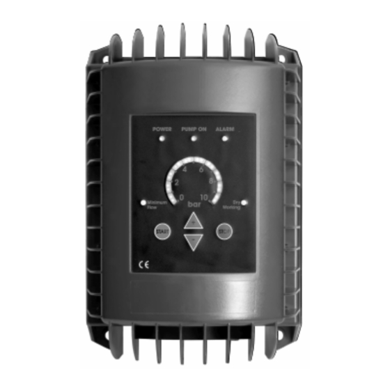
STARTING AND PROGRAMMING Button Description Allow to increase the reference pressure; it allow to go up on the advanced regulation functions also Allow to reduce the reference pressure; it allow to go down on the advanced regulation functions also Starting pump; start Self-Regulation Test on the first installation or after a RESET Instant Stop of the motor pump Fig. - Page 11 5.1 Programming Make sure the pump is charged (full of water); in case the pump is not charged provide it a direct voltage supply (without Inverter) until the complete filling of water, then re-connect the pump to the Inverter; In case the pressure of the system is more than 3 BAR open the delivery to reduce it under this value, then completely close the delivery or all of the valves on the output of the pump (very important condition);...
- Page 12 5.2 Advanced regulations and control panel visualization Command Procedure Enter on Advanced Regulations & press them simultaneously for 3 seconds Press and go up with to enter on the advanced function request, as show on table 7 regulating the value of the selected function on a variation range indicated, on a scale from 0 to 10. N°...
- Page 13 Maximum output Adjustment of the maximum 10.. 20 mA 20 Ma output value of the pressure Step: 0.5 mA value of the transducer pressure transducer Pressure Adjustment of the pressure 10..20 Bar 16 Bar transducer range. Step: 0.5 Bar transducer measure range Proportional factor on the P.I.D.
-
Page 14: Protections And Alarms
PROTECTIONS AND ALARMS Alarm type with N° Protection Description ALARM led ON Current pick The logic switches off the power instantaneously if this value exceeds a peak that can damage the power electronic components. Possible high starting current or short-circuit on motor. Over-voltage The logic switches off the current if the voltage exceeds a maximum instantaneous limit beyond that can damage... -
Page 15: Declaration Of Conformity
The guarantee is excluded or interrupted in anticipation if the damage is caused to the following: External influences, non-professional installation, non-compliance with instructions, interventions by unauthorized locations, use of not original spare parts and normal wear. DECLARATION OF CONFORMITY PENTAX SPA declare that the products : FCP109 FCP111...
Need help?
Do you have a question about the FCP Series and is the answer not in the manual?
Questions and answers