Advertisement
Quick Links
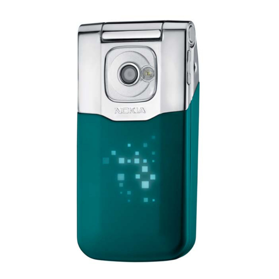
1
SERVICE MANUAL
Level 1&2
Transceiver characteristics
Band
RM-398: GSM/EDGE 850/900/1800/1900
RM-399: GSM/EDGE 850/900/1800/1900
Display
2.2" QVGA 240 x 320 display supporting up to 16M
colours
Camera
2 Mpix with 4 x digital zoom, flash
Operating System:
Series 40
Connections
Micro USB connector, 2.5 mm AV, 2 mm charging
connector, Bluetooth 2.0 + EDR
Memory
MicroSD up to 8 GB
Transceiver with BL-5BT battery pack
Talk time
Up to 6 h
Confidential
Copyright @ 2008 NOKIA. All rights reserved
7510 Supernova RM-398, RM-399; 7510a Supernova
:
:
:
:
:
Standby
Up to 300 h
Service Manual Level 1&2
Note
Depends on
network
parameters
and phone
settings
ISSUE 1
Advertisement

Related Manuals for Nokia RM-398


Summary of Contents for Nokia RM-398
- Page 1 7510 Supernova RM-398, RM-399; 7510a Supernova Service Manual Level 1&2 SERVICE MANUAL Level 1&2 Transceiver characteristics Band RM-398: GSM/EDGE 850/900/1800/1900 RM-399: GSM/EDGE 850/900/1800/1900 Display 2.2” QVGA 240 x 320 display supporting up to 16M colours Camera 2 Mpix with 4 x digital zoom, flash...
- Page 2 7510 Supernova RM-398, RM-399; 7510a Supernova Service Manual Level 1&2 Change history ..........................3 Copyright ............................4 Warnings and cautions ........................5 Warnings ..........................5 Cautions ........................... 5 ESD protection..........................6 Care and maintenance ........................7 Battery information......................... 8 Exploded view ..........................9 Service devices ..........................
- Page 3 3.9.2008 First approved version The purpose of this document is to help NOKIA service levels 1 and 2 workshop technicians to carry out service to NOKIA products. This Service Manual is to be used only by authorized NOKIA service suppliers, and the content of it is confidential. Please note that NOKIA provides also other guidance documents (e.g.
- Page 4 Nokia operates a policy of continuous development. Nokia reserves the right to make changes and improvements to any of the products described in this document without prior notice. Under no circumstances shall Nokia be responsible for any loss of data or income or any special, incidental, consequential or indirect damages howsoever caused.
- Page 5 7510 Supernova RM-398, RM-399; 7510a Supernova Service Manual Level 1&2 3. WARNINGS AND CAUTIONS Please refer to the phone’s user guide for instructions relating to operation, care and maintenance including important safety information. Note also the following: 3.1 Warnings 1. CARE MUST BE TAKEN ON INSTALLATION IN VEHICLES FITTED WITH ELECTRONIC ENGINE MANAGEMENT SYSTEMS AND ANTI–SKID BRAKING SYSTEMS.
- Page 6 7510 Supernova RM-398, RM-399; 7510a Supernova Service Manual Level 1&2 4. ESD PROTECTION Nokia requires that service points have sufficient ESD protection (against static electricity) when servicing the phone. Any product of which the covers are removed must be handled with ESD protection.
- Page 7 7510 Supernova RM-398, RM-399; 7510a Supernova Service Manual Level 1&2 5. CARE AND MAINTENANCE This product is of superior design and craftsmanship and should be treated with care. The suggestions below will help you to fulfil any warranty obligations and to enjoy this product for many years.
- Page 8 7510 Supernova RM-398, RM-399; 7510a Supernova Service Manual Level 1&2 6. BATTERY INFORMATION Note: A new battery’s full performance is achieved only after two or three complete charge and discharge cycles! The battery can be charged and discharged hundreds of times but it will eventually wear out.
- Page 9 7510 Supernova RM-398, RM-399; 7510a Supernova Service Manual Level 1&2 7. EXPLODED VIEW See corresponding ITEM/CIRCUIT REF in the Spare Parts Service Bulletins on NOL. ISSUE 1 Confidential Copyright @ 2008 NOKIA. All rights reserved...
- Page 10 7510 Supernova RM-398, RM-399; 7510a Supernova Service Manual Level 1&2 8. SERVICE DEVICES FLS-5 Flash device ACF-8 Universal power supply BL-5BT Battery RJ-230 Universal soldering jig CA-101 Service cable AC-3 Travel Charger NMP standard toolkit (v2) For more information, refer to the Service Bulletin (SB-011) on NOKIA Online.
- Page 11 Flash concept – (Point of Sales) To use the FLS-5 Flash Dongle, you have to follow the user guide inside the sales package. Please check always for the latest version of flash software, which is available on Nokia Online. ISSUE 1 Confidential Copyright @ 2008 NOKIA.
- Page 12 7510 Supernova RM-398, RM-399; 7510a Supernova Service Manual Level 1&2 10. DISASSEMBLY INSTRUCTION 1) Release the E-COVER ASSY in the direction as shown. 2) Release the A-COVER ASSY in the direction as shown. It is very tricky for the first time. A- and E-COVER ASSYs are “X-Press-on-covers”.
- Page 13 7510 Supernova RM-398, RM-399; 7510a Supernova Service Manual Level 1&2 7) Put the SS-93 Tool between the SHEET WINDOW ASSY 8) Slide along the side of the SHEET WINDOW ASSY. Be and B-COVER TRIM ASSY to detach the adhesive in the very careful not to damage the LCD.
- Page 14 7510 Supernova RM-398, RM-399; 7510a Supernova Service Manual Level 1&2 13) Do the same on the opposide to release the top of 14) Open the three clips of the B-COVER ASSY. Be the B-COVER TRIM ASSY. careful! 15) B-COVER TRIM ASSY can be taken away and has to 16) Remove VOLUME KEY with Tweezers.
- Page 15 7510 Supernova RM-398, RM-399; 7510a Supernova Service Manual Level 1&2 19) Disconnect the B2B CONNECTOR FLEX ASSY on the 20) Use Torx 6+ screwdriver to remove the screws in bottom side. Be careful with the sourrounding the shown order. components!
- Page 16 7510 Supernova RM-398, RM-399; 7510a Supernova Service Manual Level 1&2 25) Remove the PWB. 26) Use a DC plug to release the DC JACK as shown. 27) Release the AV CONNECTOR by pushing it from the 28) Remove CLIP DEKO COVER with Tweezers.
- Page 17 7510 Supernova RM-398, RM-399; 7510a Supernova Service Manual Level 1&2 31) Remove ANTENNA MODULE ASSY. After 32) Release the CABLE CAP with a Dental Pick. disassembling it has always to be renewed. 33) Remove CABLE CAB. 34) Use a Dental Pick to detach the snaps of the CAMERA SOCKET and lift it up.
- Page 18 7510 Supernova RM-398, RM-399; 7510a Supernova Service Manual Level 1&2 37) CAMERA SOCKET can be taken away. Do not use CAMERA SOCKET again. ISSUE 1 Confidential Copyright @ 2008 NOKIA. All rights reserved...
- Page 19 7510 Supernova RM-398, RM-399; 7510a Supernova Service Manual Level 1&2 11. ASSEMBLY HINTS Use TORX 4+ screwdriver to tighten the four screws. Use Torx 6+ screwdriver to tighten the screws in the shown order. ISSUE 1 Confidential Copyright @ 2008 NOKIA. All rights reserved...
- Page 20 7510 Supernova RM-398, RM-399; 7510a Supernova Service Manual Level 1&2 12. SOLDER COMPONENTS 7510 Supernova RM-398/RM-399 components overview Solder components only for Level 2 ISSUE 1 Confidential Copyright @ 2008 NOKIA. All rights reserved...
Need help?
Do you have a question about the RM-398 and is the answer not in the manual?
Questions and answers