Table of Contents
Advertisement
Quick Links
Advertisement
Table of Contents

Related Manuals for AOTAI Pulse MIG AMIG350PS


Summary of Contents for AOTAI Pulse MIG AMIG350PS
-
Page 2: Dear Customer
Dear Customer This instruction manual will help you get to know your new machine. Read the manual carefully and you will soon be familiar with all the many great features of your new product. Meanwhile, please remember well safety rules and operate as instruction. If you treat your product carefully, this definitely helps to prolong its enduring quality and reliability–things which are both essential prerequisites for getting outstanding results. -
Page 3: Safety Rules
Safety Rules Danger “ ” indicates an imminently hazardous situation which, if not avoided, will result in death or serious injury. Warning ! “ ” indicates a possible hazardous situation which, if not avoided, could result in death or serious injury. The possible hazards are explained in the text. Caution “... - Page 4 Do not place your body between your electrode and work cables. Equipotential bonding Workpiece grounding (earthing) Shielding Shield the entire welding equipment and other equipment nearby. ARC rays can burn • Visible and invisible rays can burn eyes and skin. •...
- Page 5 Hot parts can burn • Do not touch hot parts with bare hand or skin. • Ensure equipment is cooled down before perform any work. • If touching hot parts is needed, use proper tools and/or wear heavy, insulated welding gloves and clothing to prevent burns.
-
Page 6: Table Of Contents
Contents 1- GENERAL REMARKS..............................6 1-1 Power source features............................6 1-2 Functional principle............................6 1-3 Output characteristics............................6 1-4 Duty cycle................................7 1-5 Applications................................. 7 1-6 Warning label..............................8 2-VERSIONS BRIEFS..............................8 3-BEFORE COMMISSIONING............................8 3-1 Utilization for intended purpose only....................... 8 3-2 Machine installation rules..........................8 3-3 Power source connection..........................9 3-4 Welding cables instruction.......................... -
Page 7: 1- General Remarks
1- GENERAL REMARKS This series welding machines apply IGBT soft switch inverter technology; the power source enjoys highly stable welding voltage against the fluctuation of power grid and arc length change. The internal control system achieves precise control of welding process to ensure optimal welding results. 1-1 Power source features Highlights as follows: - Friendly operation interface, unified and separate adjustment modes, easy to master. -
Page 8: Duty Cycle
1-4 Duty cycle Duty cycle is percentage of 10 minutes that a machine can weld at rated load without overheating. If overheats, thermostat(s) will open, output stops. Wait for fifteen minutes for the machine to cool down. Reduce amperage or duty cycle before welding. -
Page 9: Warning Label
1-6 Warning label The warning label is affixed on the top of machine. Fig. 1-6-1: Warning label 2-VERSIONS BRIEFS Professional welding of special materials requires special welding parameters. Different models of the power sources are matched to different weldings. ● AMIG350/500PS Standard operation panel, easy to operate. -
Page 10: Power Source Connection
The venting duct is very important for safety protections. When choosing the machine location, make sure it is possible for the cooling air to freely enter and exit through the louvers on the front and back of machine. Any electro conductive metallic dust like drillings must not be allowed to get sucked into the machine. -
Page 11: Amig350/500Ps
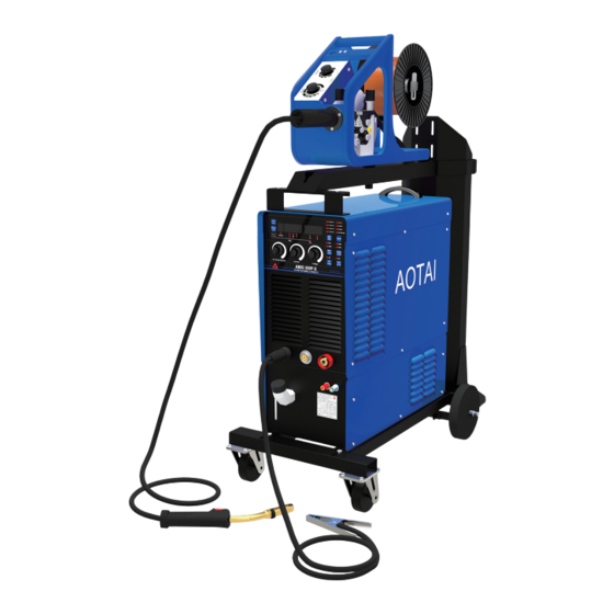
4 – AMIG350/500PS 4-1 System components This series welding machine can be equipped with many different accessories and can be used in different special sites with different configurations. Fig. 4-1-1: System components 4-2 Basic equipments for welding Only be equipped with the necessary accessories, can the power source AMIG350/500PS operate well. The following is the needed accessories list. - Page 12 Fig. 4-3-1: Control panel 1.Wire diameter selection button Can select relative wire diameter, corresponding indicator will light on. 2.Welding material selection button Select the welding wire material used. 3.Operating mode of welding torch Graphic symbol Fig. 4-3-2 Press torch trigger Fig. 4-3-3 Hold torch trigger Fig. 4-3-4 Release torch trigger P03……Pre-gas time P17……Initial parameter: The base metal can be heated up rapidly, despite the fast thermal dissipation at the start of...
- Page 13 Fig. 4-3-5: 2-step mode - 4-step mode(starting indicator: OFF;crater filling indicator :ON) Fig. 4-3-6: 4-step mode - Special 4-step mode ((starting indicator: ON;crater filling indicator :ON)) Fig. 4-3-7: Special 4-step mode - Spot welding mode Fig. 4-3-8: Spot welding mode 4.Solid core/flux cored wire selection button Choose solid core wire or flux cored wire, the corresponding indicator light will be on.
- Page 14 9.Initial / Crater filling selection button When the initial indicator light is on, the current and voltage knobs on the control panel can set the initial specifications. P17 can preset the time. When the arc closing indicator light is on, the current and voltage knobs on the control panel can set the arc closing specifications.
-
Page 15: Sub Menu
16."V" indicator When the indicator light is on, it displays the voltage or voltage offset. 17." " indicator When the indicator light is on, the arc force can be adjusted. 18."Crater filling" indicator ISA Bus & Address Decoding Protel International P/L Title L3, 12a Rodborough Rd When the indicator light is on, the current and voltage knobs on the control panel can set the crater filling specifications. - Page 16 stick with the work piece. - P02 Slow wire feeding With too quick feeding speed, the wire will be easily exploding with failed arc-starting; if the feeding speed is slower than the melting speed, the long arc will cause conductive tip burned. - P03 Gas pre-flow time Longer time will cause waste of gas and low efficiency;...
-
Page 17: Save&Call Function
● Enter sub menu Press“MENU” button for 3s, then enter sub-menu. Fig. 4-4-1: Enter sub menu Fig. 4-4-2: Select parameters Fig. 4-4-3: Adjust value ● Sub menu parameters adjustment Adjust “current” knob to select parameters between P01 to P35; Adjust “voltage” knob to adjust value of corresponding parameter. ●... -
Page 18: Shift Between Preset Current And Preset Wire Feeding Speed
Fig. 4-5-2 Call function 4-6 Shift between preset current and preset wire feeding speed Press the “current” for 3s; the current display will display the preset current and the preset wire feeding speed alternately. Fig. 4-6-1 shift display 4-7 Reset to factory setting Press“Arc force”... -
Page 19: Interface
4-8 Interface Fig. 4-8-1: Interface 1.Control panel 2.Quick socket (-) It is used to connect with workpiece. 3.Quick socket (+) It is used to connect with wirefeeder. 4.Control socket It is used to connect with wirefeeder. 5.Fuse Control transformer fuse, protect control circuit parts. 6. - Page 20 ●MIG/MAG welding process installation Fig. 4-9-1: Installation for MIG/MAG ● Mounting the torch To ensure normal welding, please make sure that the wire diameter, contact tip, welding torch, welding wire tube are matched to each other.. Choose wire feeding tubes according to wires of different diameters and materials. - Steel wire hose is suitable for hard wire, such as carbon steel wire, stainless steel wire.
- Page 21 4. Screw the pressure regulator onto the gas cylinder and tighten it. 5. Connect the shielding-gas connector to the pressure regulator. Fig. 4-9-3: Gas cylinder installation ● Installation environment requirements 1. It should be placed indoors without direct sunlight, rainproof, low humidity and less dust. The ambient air temperature range is -10℃~+40℃.
-
Page 22: Technical Data
4-10 Technical data Model Voltage/Frequency (3~) AC380/400/415V±10%,50Hz Rated input power (KVA) Rated input current(A) 21/20/19 38/36.6/34.7 Range of welding current(A) 60~350 60~500 Range of welding voltage(V) 17~31.5 17~39 OCV(V) Duty cycle (%) Full-load efficiency(%) ≥87 Power factor ≥0.95 Wire diameter (mm) Ф0.8,Ф1.0,Ф1.2 Ф1.0,Ф1.2,Ф1.6 Gas flow(L/min) -
Page 23: Disassembly And Reassembly
4-12 Disassembly and reassembly Fig. 4-12-1: Disassemble and reassembly... - Page 24 Item Stock No.for 500 Remarks Left plate 262017-00056 Top plate 262029-00290 Handle 766003-00138 Resonance capacitor 722001-00074 Main transformer 220629-00042 Resonance inductor 220521-00040 Main control board 210580-00311 Power transformer I 763001-00068 Drive board 210310-00069 Power transformer II 715004-00178 Solid state relay 763001-00014 Circuit breaker support 766003-00188...
-
Page 25: 5-Trouble Shooting
5-TROUBLE SHOOTING Warning! An electric shock can be fatal. Before doing any work on the machine: -Switch it off and unplug it from the mains -Put up a clearly legible and easy-to-understand warning sign to stop anybody inadvertentlyswitching it on again -Check to make sure the electrically charged components (e.g.capacitors) have been discharged. - Page 26 ● Power source trouble shooting Note! The flowing troubles and causes are uncertain. However, during the process of MIG Pulse and the normal using conditions, that might happen. Problem Cause Remedy The arc is unstable; 1. Stainless steel: Ar+(2.5)%CO2 The forming color of the weld 2.
-
Page 27: 6-Care And Maintenance
6-CARE AND MAINTENANCE Before open the machine Warning! An electric shock can be fatal. Before doing any work on the machine: -Switch it off and unplug it from the mains -Put up a clearly legible and easy-to-understand warning sign to stop anybody inadvertently switching it on again -Check to make sure the electrically charged components (e.g.capacitors) have been discharged.
Need help?
Do you have a question about the Pulse MIG AMIG350PS and is the answer not in the manual?
Questions and answers