Table of Contents
Advertisement
Advertisement
Table of Contents

Related Manuals for AOTAI ASP-8KTLC


Summary of Contents for AOTAI ASP-8KTLC
- Page 1 Grid-tied PV Inverter ASP-8/10/12/15KTLC Operating Manual...
-
Page 2: Table Of Contents
ASP-8/10/12/15KTLC Thank you for choosing AOTAI non-isolated on-grid PV inverter. In order to ensure your safety and proper use, please read the manual in details before using. Thanks your cooperation! Contents 1. Overview....................3 1.1 Use of this manual................3 1.2 Symbols................... 3 1.3 Nameplate.................. - Page 3 ASP-8/10/12/15KTLC 6. Operating guide..................31 6.1 Working modes................31 6.2 Power generation process.............. 33 6.3 Disconnect from grid..............33 7. Maintenance and Repair................33 7.1 Maintenance...................34 7.2 Troubleshooting................34 8. Appendix....................36 8.1 Technical Parameters..............36 8.2 Quality Assurance................38...
-
Page 4: Overview
ASP-8/10/12/15KTLC 1. Overview 1.1 Use of this manual This manual mainly introduces installation, operating and maintenance of ASP-8/10/12/15KTLC and related technical parameters. It is suitable for people who install the inverters and do other related jobs. Readers need to have some knowledge of electric, electrical wiring and mechanics. Before installing this product, please read this manual carefully, and put it in a suitable place, so as to ensure that relevant personnel of installation and operation can easily get it. -
Page 5: Nameplate
ASP-8/10/12/15KTLC It means that there is low level of potential danger. If not listen to this warning, it might cause personal injury or serious financial loss. ATTENTION It means there is potential risk. If not listen to this warning, it might cause financial loss. -
Page 6: Delivery
ASP-8/10/12/15KTLC 2. Delivery 2.1 Scope of Supply There are following items in the packing box, as shown in Table 2-1. Please check in time after receiving the products. Order Name Note PV on-grid inverter Operating manual Product qualification certificate Fixed plate Factory inspection report Male/female cable connector, 2/3 PV cable connector... -
Page 7: Product Acceptance
So, please check them when sign for them. If there is any damage, please contact the shipping company or directly contact AOTAI. Please provide photos of the damaged parts, and we will provide the best service as fast as... -
Page 8: Description
ASP-8/10/12/15KTLC 3. Description 3.1. Brief Introductions On-grid PV power generation system usually is composed of solar panels, junction box, inverter, ammeter and power grid. The core of the system is PV grid-connected inverter. The sunshine irradiates on the surface of the solar panels, solar panels output DC, converted by inverter, then output AC of the same frequency and phase with the grid, and then feed into the grid. - Page 9 ASP-8/10/12/15KTLC Product performance Transformerless, highest efficiency is 98.5% Wide input voltage, MPPT efficiency is 99.9% Two way independent MPPT control to deal with different installation angles, enhance power generation Active and passive anti-islanding protection technology Comprehensive protection, higher reliability ...
-
Page 10: General Introduction
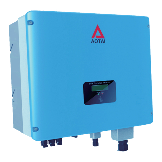
ASP-8/10/12/15KTLC 3.2 General Introduction Appearance and interface Fig 3-2 Appearance of ASP-10 KTLC Appearance of ASP-8/10/12/15KTLC (take ASP-10KTLC for example) is as shown in Figure 3-2. Its external interface is in the bottom of the machine and is composed of PV input port +, PV input port-, communication port, DC switch. Please refer to Figure 3-3 and Table 3-1 for details. - Page 11 ASP-8/10/12/15KTLC Fig 3-3: External Port Name Description Inverter’s DC input port, connect PV input port + with + port of solar panels. Inverter’s DC input port, connect PV input port - with – port of solar panels. 8-10KTLC inverter is Nylon DC input port stopper head;...
-
Page 12: Installation
ASP-8/10/12/15KTLC 4. Installation Please carefully read below installation guide for ASP-8/10/12/15KTLC. 4.1 Installation Procedure Start Preparations Mechanical installation Electrical connections Check after installation Commissioning with power Finish Fig 4-1 Installation procedure... -
Page 13: Installation Preparation
ASP-8/10/12/15KTLC 4.2 Installation Preparation ● Check whether there is damage during transport Although we have carefully tested and inspected the inverter before shipping, there might be damage during transport. So please check them before installation. If there is any damage, please contact the shipping company or directly contact us. Please provide photos of the damaged part. - Page 14 ASP-8/10/12/15KTLC Installation place should not shake. Installation height is better to make the LCD at the same level with people’s eye so as to make it convenient to operate on the LCD. Requires good ventilation The ambient temperature should be between -25℃ ~+60℃...
- Page 15 ASP-8/10/12/15KTLC ATTENTION Ambient temperature range should be -25℃ ~ +60 ℃. If out of the range, it will affect power generation. Installation environment needs to be clean; The inverter needs to be installed uprightly, and cannot be placed horizontally or upside down, or tilted.
- Page 16 ASP-8/10/12/15KTLC Multiple inverters can be installed side by side, and multiple rows of inverters need to be installed staggered to facilitate heat dissipation. Do not install the inverter in the place where children can touch so as to avoid scald or electric shock.
-
Page 17: Mechanical Installation
ASP-8/10/12/15KTLC DANGER Don't put inverter together with inflammable, explosive goods. CAUTION During working, the inverter is of high temperature. Please do not touch it! 4.3 Mechanical Installation 4.3.1 Safety Touch any part of the inverter may cause deadly injury. DC side voltage of the inverter is up to 1000V, and AC side 450V. -
Page 18: Dimensions
ASP-8/10/12/15KTLC 3. Maintenance must be done by professional people. 4. Grid connection of this inverter must be allowed by local power supply departments. 5. When installing solar panels during the day, please cover the panels with lighttight materials. Otherwise, there will be very high voltage at the panel and cause personal danger. -
Page 19: Installation
ASP-8/10/12/15KTLC Figure 4-2 Inverter size 4.3.3 Installation Fixed plate and fasteners like expansion bolts are used to install the inverter vertically on the wall or metal stents. Bolts are M8 x 30, as shown in figure 4-3. - Page 20 ASP-8/10/12/15KTLC Figure 4-3 Fixing plate mounting hole position If install the inverter on concrete wall, firstly mark drill hole on the wall according to fixed plate size, and drill at marked locations, then fix plate on wall with M8*30 expansion bolts, and then hang the machine on the plate.
-
Page 21: Electrical Connection
ASP-8/10/12/15KTLC If install on metal scaffolds, similar to drilling on wall, drill according to fixed plate size, fix plate with M8 bolts, and hang the machine on the plate. 4.4 Electrical Connection 4.4.1 Electrical Connection Requirements Take ASP - 10 KTLC for example. ... - Page 22 ASP-8/10/12/15KTLC Power grid voltage: 310 V - 480 VAC, Power grid frequency: 45-55 Hz / 55-65 Hz Cable: AC and DC wiring should conform to local safety standards. Wire diameter should guarantee basic flow capacity. Table 4-1 Cable specification Cable ASP-8/10/12/15KTLC PV Array+...
-
Page 23: Wire Connection
ASP-8/10/12/15KTLC 4.4.2 Wire Connection Note: Grid’s Phase L1 is yellow line, Phase L2 is green line, Phase L3 is red line, N wire is black line, and the ground wire is yellow& green line. AC Wiring Disconnect breaker on AC side, measure with multimeter and ensure that there is no power on AC wires that connect with terminal. - Page 24 Fix AC cover well and screw up AC waterproof joint, as shown in below. Distance between inverter and grid connecting point, corresponsive Model cable(cable diameter: mm 2 ) 10m-30m 30m-50m 50m-80m Above 80m When there is only one inverter ASP-8KTLC in the project, try to avoid...
- Page 25 Ensure PV array’s polarity match with inverter DC connectors. Ensure each PV string voltage won't exceed 1000V. DC connector must be provided by AOTAI. It is forbidden to connect PE wire (ground wire) to positive and negative poles of PV arrays, otherwise it will cause inverter damage.
- Page 26 ASP-8/10/12/15KTLC Step2: Cable ends are clustered at terminal with pressure clamp. Step 3: Pass cable through cable seal sleeve. Step 4: Insert terminal into insulated sleeve until it is fastened and gently pull the cable to ensure it is firmly connected. Step 5: Tighten sealing sleeve and insulation sleeve.
- Page 27 ASP-8/10/12/15KTLC For PV cable connection, positive and negative polarities must be correctly connected. Step 7: Disconnect DC breaker. Step 8: Double check whether polarity of PV string connection cable is correct. Ensure open circuit voltage not exceeding 1000V even under lowest working temperature.
-
Page 28: Inverter Commissioning
ASP-8/10/12/15KTLC 4.5. Inverter Commissioning 4.5.1 Check before Commissioning As previously mentioned installation procedure, correctly connect PV arrays, inverter and AC grid. Ensure that AC and DC voltages meet the need of machine start. PV array Before start the inverter, it needs to check PV arrays on site and see whether open-circuit voltage of every PV cell is ok. -
Page 29: Commissioning
ASP-8/10/12/15KTLC 4.5.2 Commissioning 1. Ensure above checking items to comply with the requirements. 2. Turn on the breaker and DC switch at the DC input side. 3. Turn on the breaker at grid side. 4. When all requirements for its normal operation are satisfied, the inverter will automatically start up and generate power. -
Page 30: Monitoring
ASP-8/10/12/15KTLC 5. Monitoring 5.1 Overview The inverter has many communication modes. When users need to monitor the operation of PV power generation system, we will offer below communication system. Fig.5-1 RS485 (Standard MODBUS Protocol) communication system mode Fig. 5-2 WIFI/GPRS communication system mode 1.Communication between on-grid inverters can be realized by Standard MODBUS protocol RS485, so as to conduct real-time monitoring of the inverters’... -
Page 31: Lcd Display Panel
ASP-8/10/12/15KTLC 2.GPRS/WIFI communication pls check WIFI RTU Instruction or GPRS RTU Instruction. 5.2 LCD Display Panel TLC series are equipped with LCD panel according to customers’ needs with 2 LED indicators and 1 acoustic sensing area. LCD display LED Indicator Switch 5-3 TLC series LCD panel LED display status and display meaning are as shown in Table 5-1. -
Page 32: Operating Guide
ASP-8/10/12/15KTLC 6. Operating guide 6.1 Working modes Inverter working modes include: “Start-up”, “Running”, “Stand-by”, “Fault” and “Stop”. LCD shows corresponding info in each working mode. ATTENTION The data in the Figure and Table is just for reference. Take ASP -10KTLC for example. ... - Page 33 ASP-8/10/12/15KTLC Running In this mode, inverter converts DC power from PV arrays to AC to feed into power grid. Meanwhile, inverter continuously outputs max. energy by MPPT. LCD on the inverter refreshes every two seconds on Running mode, so all information is valid in current two seconds.
-
Page 34: Power Generation Process
ASP-8/10/12/15KTLC 6.2 Power generation process On gird generating capacity process is automatic, described as follows: 1. Switch on DC and AC circuit breakers, the inverter will enter startup mode. 2. If input voltage on DC side exceeds 300V, AC side voltage in range 310V- 480Vac, and grid frequency is normal, inverter begins countdown. -
Page 35: Maintenance
ASP-8/10/12/15KTLC 7.1 Maintenance Due to environment temperature, humidity, dust and vibration, aging and wear are the common problems of inverter’s internal components, and this will affect the inverter’s life span. Therefore, regular maintenance is very important to ensure the inverter’s normal running and lifespan. ... - Page 36 ASP-8/10/12/15KTLC Fault Solution 1. Disconnect the AC circuit breaker 2. Disconnect the DC circuit breaker LED indicator and 3. Check the PV array input voltage (whether LCD screen light lower than 200V) are not on 4. If all the above are ok, check whether the breaker is good 1.
-
Page 37: Appendix
ASP-8/10/12/15KTLC 4.Check whether machine ventilation, articulated installation, and air duct are ok 5. Check whether the output power is higher than the rated value 1. Disconnect the AC circuit breaker 2. Disconnect the DC circuit breaker Ground Fault 3. Check whether resistance of each group of PV arrays to the ground is >... - Page 38 ASP-8/10/12/15KTLC Output Data Rated output power 8000W 10000W 12000W 15000W Max. AC power 8.8KVA 11KVA 13.2KVA 16.5KVA Max. output current 19.2A Rated power grid 400Vac voltage Power grid voltage 310Vac~480Vac range Rated power grid 50Hz/60Hz frequency Grid frequency range 45~55Hz/55~65Hz <2%(Under the rated power) Power factor 0.8(Leading)~0.8(Lagging)...
-
Page 39: Quality Assurance
This standard warranty period is 60 months. If it is specified in the contract, please take it as standard. Conditions AOTAI will offer free repair service or replace with new product for faults during the warranty. The replaced unqualified product will be returned to AOTAI. - Page 40 ASP-8/10/12/15KTLC Improper installation Improper modification Incorrect use Very harsh environment that is beyond the specified in this manual Any installation and use that is beyond the relative international standards Damages caused by improper natural environment...
- Page 41 Thank you for taking time to share your feedback. Your comments and suggestions will help us to serve you better. Please send fax or e-mail your feedback, we will response you within 24 hours. Contact Information Aotai Electric Co., Ltd. Global Sales Department Tel: +86-531-81921036 Fax: +86-531-81921022 www.aotaielectric.com...
Need help?
Do you have a question about the ASP-8KTLC and is the answer not in the manual?
Questions and answers