
Related Manuals for SHEKEL Healthweigh 551


Summary of Contents for SHEKEL Healthweigh 551
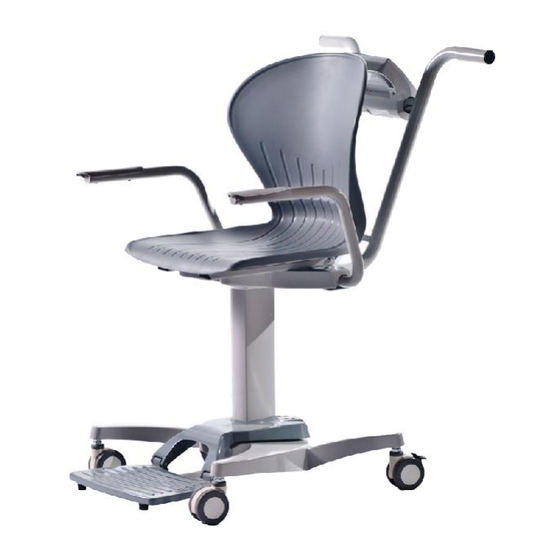
- Page 1 Calibration instructions on page 37. SERVICE MANUAL ® Healthweigh Chair Scale Model 551 ® CAT: AA0448-1 SERVICE MANUAL HEALTHWEIGH MODEL 551 Page 1 of 36...
- Page 2 TABLE OF CONTENTS CHAPTER 1: INTRODUCTION ________________________________________________ 4 CHAPTER 2: DIAGNOSIS ____________________________________________________ 5 CHAPTER 3: REPAIR PROCEDURES _________________________________________ 7 Titanium Indicator________________________________________________________________7 Replacing Wheels _______________________________________________________________11 Replacing foot platform__________________________________________________________11 Replacing Seat__________________________________________________________________13 Replacing Indicator arm _________________________________________________________14 Replacing a chair arm ___________________________________________________________14 Replacing load cell ______________________________________________________________15 Replacing the pillar______________________________________________________________17 CHAPTER 4: TESTING AND CALIBRATION PROCEDURE _____________________ 19 CHAPTER 5: DRAWINGS AND PARTS LISTS _________________________________ 20...
- Page 3 INTRODUCTION This service manual contains the information needed to perform routine maintenance and service on the Healthweigh® Chair Scale. This service manual is intended for exclusive use by certified personnel. No responsibility can be taken if the manual is used by unauthorized persons. Chapter 1 Introduction –...
- Page 4 CHAPTER 1: INTRODUCTION TOOLS AND TEST EQUIPMENT REQUIRED ® In order to service the Healthweigh Handrail scales, various tools and items are required in and are as follows: Special Tools and Test Equipment List Alternate voltage Power Adapter, #UE15WCP-090050SPA ...
- Page 5 CHAPTER 2: DIAGNOSIS TROUBLESHOOTING This section of the service manual specifies problems which can occur in the scales. DIAGNOSTIC GUIDE The diagnostic guide is designed to help locate the problem quickly and easily. First locate the symptom; then review the probable cause and remedy. The probable causes are listed with the most common cause first.
- Page 6 DIAGNOSTIC GUIDE SYMPTOM POSSIBLE CAUSE CORRECTIVE ACTION Scale does not turn on Dead battery Connect scale to power source Faulty electrical outlet Use a different outlet Bad power supply Replace adaptor Questionable weight or External object interfering with the scale Remove interfering object from the scale does not zero the scale...
- Page 7 The procedure for upgrading or installing the firmware can be found in Appendix 6. Before starting to repair the indicator: Turn off the scale and remove the power adapter. Important: Repairing the indicator requires breaking the Shekel seals which nullifies the warranty of the scale.
- Page 8 First, disconnect the battery connector. Then remove the battery holder by unscrewing the two screws. To remove the battery insert a flat screw driver beneath the battery and pop it out. To disconnect the indicator unscrew the four (4) screws attaching it to the scale frame. ®...
- Page 9 To expose the indicator circuit open the five (5) peripheral screws ® CAT: AA0448-0 SERVICE MANUAL HEALTHWEIGH MODEL 551 Page 9 of 36...
- Page 10 Removing the circuit: Disconnect the keypad braid from the circuit. Unscrew the four (4) screws that attach the circuit to the front panel. ® CAT: AA0448-0 SERVICE MANUAL HEALTHWEIGH MODEL 551 Page 10 of 36...
- Page 11 Replacing Wheels Unscrew the wheel from its housing. If the wheel is locked with a nut, use an open key to unscrew the wheel unit. Replace the wheel and screw it back to its housing. Remember to use the narrow nut Replacing foot platform Foot bumper Unscrew the screw and replace the bumper.
- Page 12 ® CAT: AA0448-0 SERVICE MANUAL HEALTHWEIGH MODEL 551 Page 12 of 36...
- Page 13 Feet rest to the load cell cover To replace a complete foot rest unscrew the screws acting as hinges. Before replacing the foot rest check for the friction washer on the side of each foot rest hinge Screw in the two (2) screws Replacing Seat The seat is attached to the seat platform with four (4) screws.
- Page 14 Replacing Indicator arm Before replacing the indicator arm – unthread the load cell wire. Refer to replacing the seat – to remove the seat. For Class III models: Refer to replacing an indicator – to disconnect the load cell wire from the indicator, and disconnecting the indicator from the indicator arm Unscrew the two (2) screws that secure the indicator arm in place.
- Page 15 Replacing the hand rest on the arm handle Unscrew the two screws securing the hand rest to the arm handle. Position the new hand rest; make sure the curve is facing outward from the chair. Screw in the two (2) screws securing the hand rest. As you screw in the screws be careful that the screws do not penetrate the hand rest.
- Page 16 Seat is removed- For Non-Class III disconnect the load cell from the indicator cable For Class III disconnect the load cell cable from the indicator and thread it out ® CAT: AA0448-0 SERVICE MANUAL HEALTHWEIGH MODEL 551 Page 16 of 36...
- Page 17 Detaching the load cell from the wheel base: Turn over the chair for better access to the load cell anchoring bolts. Break the seal and using an Allen key open the four (4) anchoring screws of the load cell. After replacing the load cell, screw in the four (4) screws with lock washers, tightened to 32 [N- m] locking moment Replacing the pillar Before replacing the pillar...
- Page 18 Disconnect the load cell from the load cell cover by unscrewing in the four (4) Allen screws Disconnect the pillar from the load cell cover by unscrewing the four (4) Allen screws using an Allen key. Replace the pillar. Assemble it to the load cell cover using the same four (4) Allen screws. Thread the load cell cable Assemble the load cell with the four (4) Allen screws with lock washers, tight to 32 [N-m] locking moment...
- Page 19 CHAPTER 4: TESTING AND CALIBRATION PROCEDURE Important: Scales with OIML Class III compliance have a seal to prevent any unauthorized person from performing calibration. Please note the scales have been calibrated according to your local gravitational force. If the scales are moved into another geographical area please check with your dealer if the same gravitational force applies.
- Page 20 CHAPTER 5: DRAWINGS AND PARTS LISTS This section contains exploded view and parts lists for the Titanium Indicator. The exploded view drawing is designed to identify the parts which can be serviced in the field. Note: In all cases where a part is replaced, the scale must be thoroughly checked after the replacement is made.
- Page 21 ® CAT: AA0448-0 SERVICE MANUAL HEALTHWEIGH MODEL 551 Page 21 of 36...
- Page 22 APPENDIX 1: TITANIUM INTERCONNECTION ® CAT: AA0448-0 SERVICE MANUAL HEALTHWEIGH MODEL 551 Page 22 of 36...
- Page 23 APPENDIX 2: KEY DESCRIPTION End user operation mode: On/Off - Turns the scale on or off. LB\KG – Print A short press allows toggling between pounds and kilograms (providing it is enabled in configuration mode). It is not possible to toggle in BMI mode. A long press will trigger a transmission of data sent out by RS232 (refer to RS232 protocol in Appendix 5).
- Page 24 BMI procedure: LB mode Patient steps on scale while zero flag is on. Weight is displayed (without lock annunciator turned on). Pressing on BMI key will enter BMI mode. BMI and FT indicators are on and the height default value, 5ft 7.5in, will be displayed.
- Page 25 APPENDIX 3: PARAMETERS LIST AND CALIBRATION The measuring unit of the menu will be according to the measuring unit of the last calibration. Maintenance menu While the scale is initializing, hold the ENTER button for 3 seconds until ID with firmware ID number flashes on the display. ID (99999) Firmware id number RID(99999)
- Page 26 "PROG" parameters: Programming menu – PROG FULL Full capacity (*) LOAD Calibration Load - maximum full capacity (*) Can also be changed from the calibration menu. G-CAL (00000) Gravity value on calibration site (Only showing the value after decimal point 9.00000, fixed 9)(*) G-LOC (00000) Gravity value on local site (Only showing the value after decimal point 9.00000,...
- Page 27 ANTI-KEY PRESSING EFFECT (If tare option is on and in weighing mode) 1. Weight under ASTART value will flash zero when unstable or stable under two seconds. 2. On stable weight for more than two seconds will display the weight. GRAVITY COMPENSATION: 1.
- Page 28 "CALIB" process: Calib 'ENTER' 'UP'\'DOWN' KG or LB selection stage 200.0 LB 100.0 KG 'ENTER' Calibration Load selection stage Use UP, DOWN and LEFT 200.0 LB arrow keys to change load value 'ENTER' A request to clear the CLEAR scales weighing platform 'ENTER' Getting data stage will move =====...
- Page 29 CALIBRATION WITH GRAVITY FUNCTION Step 1 - In Maintenance menu: Enter CALIB function: CALIb G-CAL xxxxx For case – For case – GUPdt (OP 11) set GUPdt (OP 11) xxxxx 79493 to ON (1) set to OFF (0) G-CAL value - Insert gravity value of initial calibration position Example:(9.)79493 ISRAEL gravity...
- Page 30 Step 2 - For GUPdt set to 1 (ON) – Enter USER menu GrAv function GrAv Value entered at G-CAL xxxxx Calibration Process- Locked value G-LOC xxxxx Enter local gravity (9.)xxxxx * SAVE DONE * Once the value has changed and saved, the function GrAv is set to OFF. Values are set and to change them you need to recalibrate.
- Page 31 APPENDIX 4: BATTERY HANDLER 7.2 rechargeable dry batteries 6 batteries X 1.5v AA 6 X AA1600[mAh] Battery Flag status indicator Voltage range [AD/16] [AD/16] Voltage range [v] Max. Min. Max. Min. Maximum 3 bars are 3482 2787 battery 3290 2631 value Medium 2 2 bars are...
- Page 32 APPENDIX 5: COMMUNICATION RS232 Communication The Scale Communication Protocol is used to send data between the scale and the PC or printer that it is connected to. The baud-rate of the communication is programmable, the default value is 9600. The remaining communication parameters are fixed, 8 data bit, 1 stop bit and no parity.
- Page 33 Communication protocols: The scale has two communication protocols - ESC Protocol and Maintenance protocol. ESC Protocol An Escape protocol is where the escape (0X1B or ASCII 27) is used to indicate that there is a command following. The vendor should have an interface on the PC side that will communicate with this protocol.
- Page 34 Name of Control Identifier Unit Unit Of Measure (Metric or constitutional) c (m or c) Table A - Scale Global Values List and Identifiers Name of component to test Identifier Error Code AD value E06=AD too high; E07=AD too low Overload Battery E4L(Bat Low, but still usable –...
- Page 35 2. When the user wants to diagnose the problems on the scale, it will look like this: <SCALE> <PC> Direction of communication <ESC>ABAT<ESC>E Diagnose battery If the battery is OK, the scale will reply with the following value: <SCALE> <PC> Direction of communication <ESC>ZE4L<ESC>E Battery is low but still usable...
- Page 36 APPENDIX 6: FLASH INSTRUCTIONS Re-flash: 1. In order to burn the program you will need the following files: The firmware file (*.hex). The batch file (FlashARM.bat). The burning program (Armboot.exe). All files must be in the same directory. 2.
- Page 37 www.shekelonline.com June 2014...
- Page 38 Each country has its own definition of the authorized authority. • Please refer to Shekel Scales service manuals and/or our service dept. for any information regarding the scale before attending the scales.
- Page 39 The Titanium Display The keypad will be used in the calibration process Start by turning ON the scale On/Off Shekel Scales Ltd. www.shekelonline.com June 2014...
- Page 40 Enter the Maintenance Menu Immediately after the scale is turned on, enter the maintenance menu by pressing the ENTER key for 3-5 seconds. “Id” will flash on the screen Shekel Scales Ltd. www.shekelonline.com June 2014...
- Page 41 Locating the Calibration Button For 15x scales – Remove the battery cover. For Titanium indicators – Remove the back panel. For 65x – NO need to remove anything. Calibration button access Shekel Scales Ltd. www.shekelonline.com June 2014...
- Page 42 Access the calibration button located in the back of the indicator to enter the setup parameters of the scale. Use a cross head #1 screwdriver or a paper clip, to press the calibration button. Shekel Scales Ltd. www.shekelonline.com June 2014...
- Page 43 Parameter Menu The display will change to PROG • Press the BMI (once) to advance to “CAL lb” option • Access the calibration process by pressing the ENTER key Shekel Scales Ltd. www.shekelonline.com June 2014...
- Page 44 Calibration Process Follow the calibration process according to the service manual. Shekel Scales Ltd. www.shekelonline.com June 2014...
- Page 45 Upon successful completion of the calibration, save the calibration. • Press the ENTER key as the display will show SAVE • Reset the scale by pressing the ON/OFF key. For additional questions, please contact your dealer. Shekel Scales Ltd. www.shekelonline.com June 2014...
Need help?
Do you have a question about the Healthweigh 551 and is the answer not in the manual?
Questions and answers