
Related Manuals for Danville Signal Processing dspInstrument spDAQ


Summary of Contents for Danville Signal Processing dspInstrument spDAQ
- Page 1 Danville Signal Processing, Inc. dspInstrument spDAQ Two Channel Sound & Vibration Front End USB Bus Powered User Manual Version 1.00...
- Page 2 Danville Signal Processing, Inc. Danville Signal Processing, Inc. strives to deliver the best product to our customers. As part of this goal, we are constantly trying to improve our products. Danville Signal Processing, Inc., therefore, reserves the right to make changes to product specification or documentation without prior notice.
- Page 3 Output Channels........................2 Digital I/O..........................3 Connections............................3 Installation........................4 USB & Computer Requirements....................4 Device Drivers & Control Software.................... 4 Installation Steps........................4 Specifications......................5 dspInstrument spDAQ Control..................6 Overview..........................6 I/O Configuration........................6 Inputs..............................6 Outputs..............................6 TEDS............................7 Calibration..........................7 GPIO............................7 Calibration Procedure....................8 Overview..........................
- Page 4 A Microsoft Windows driver with ASIO support is included. This ensures jitter free performance at sample rates of 192k, 96k and 48k with full 32 bit depth. The control functions of the dspInstrument spDAQ are managed by a standalone Windows application provided by Danville Signal or may be integrated directly into the third party software Analyzer/Generator application.
- Page 5 The bias current is 4mA. When using an IEPE sensor, the bias voltage will typically be in the range of 8-12 volts DC. This allows the dspInstrument spDAQ to test for cable/sensor shorts or opens, since an open condition will be about 24V and a short will be near zero volts.
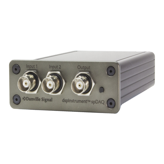
- Page 6 Digital I/O The dspInstrument spDAQ has three opto-isolated inputs and three opto-isolated outputs that are available on RJ45 connectors on the back panel. The wiring uses standard Ethernet cable conventions so that off-the- shelf CAT6 cables can be used. Since each input or output uses one pair of wires, the remaining pair provides +5V and Ground.
- Page 7 192k, 96k and 48k with ASIO. A MIDI interface is used for control. Danville also provides a Control App that is used to configure the dspInstrument spDAQ. This application supplements third party signal processing applications to select input operating modes, gain and attenuators settings, and also functions as a TEDS reader.
- Page 8 Specifications General Sampling Rate 48kHz, 96kHz, 192kHz Sampling Precision 24 bit Inputs Input Voltage (full scale) ±10 V (7.07 V Input Gain Settings x1, x2, x4, x8, x16, x32, x64, x128 (independent each channel) Input Voltage Ranges ±10V, ±5V, ±2.5V, ±1.25V, ±625mV, ±312.5mV, ±156.25mV, ±78.125mV Input Channels Connector...
- Page 9 The main purpose of this program is to select the desired operating modes and gain/level configurations of the dspInstrument spDAQ. This application is written in Microsoft Visual C with source code available for third party software providers who may wish to more tightly integrate the dspInstrument into their programs.
- Page 10 TEDS The dspInstrument spDAQ includes a TEDS reader for accelerometers and measurement microphones. These devices are supported as TEDS template 25 & 27 devices. You can read manufacturer, serial number, and device sensitivity using this function. Only one channel can read TEDS information at a time. Select the desired channel and the information will be updated automatically.
- Page 11 Keep in mind that the dspInstrument spDAQ is not a generator or an analyzer. It is the front end to a software application that collectively makes the combination a generator or an analyzer. This means that an application program will be involved in the calibration process.
- Page 12 The companion dspInstrument spDAQ Control App has a tool that quickly determines the correct scaling factors for the dspInstrument spDAQ and stores these values into non volatile memory. The program also calculates the correct scaling factors for each range based on these calibration values, but keep in mind that these values are all referenced with the assumption that the attenuators and programmable gain amplifiers have perfect accuracy.
- Page 13 Adjusting the Input Scaling Factor 1. Set the Reference Voltage (Input Section) to the reading on the DMM. This will probably be 1.0000V. 2. Set the FFT Window to Flat or Rectangular in the Analyzer/Generator application. This ensures that the level at 1004 Hz is accurate.
- Page 14 If Danville Signal Processing receives notice of such defects during the warranty period, Danville Signal Processing shall, at its option, either repair or replace software media or firmware, which do not execute their programming instructions due to such defects.
Need help?
Do you have a question about the dspInstrument spDAQ and is the answer not in the manual?
Questions and answers