
Related Manuals for Danville Signal Processing dspNexus 2/8


Summary of Contents for Danville Signal Processing dspNexus 2/8
- Page 1 Danville Signal Processing, Inc. dspNexus 2/8 DSP Audio Processor P/N A.03743A User Manual Version 1.0...
-
Page 2: Trademark Notice
Under the copyright laws, this manual may not be reproduced in any form without prior written permission from Danville Signal Processing, Inc. Danville Signal Processing, Inc. strives to deliver the best product to our customers. As part of this goal, we are constantly trying to improve our products. Danville Signal Processing, Inc., therefore, reserves the right to make changes to product specification or documentation without prior notice. -
Page 3: Table Of Contents
Table of Contents Overview.........................1 Versions........................2 Current Models............................2 Legacy Models............................2 Hardware........................3 Motherboard............................4 DSP Module.............................4 DAC Modules (Analog Outputs)......................10 Headphone Amplifier..........................11 Power supply............................11 Display, Remote & Encoder........................12 Software........................13 Installation......................15 Amplifier Connections..........................15 Input Connections..........................16 Control: Operation....................17 Display/Encoder/Remote Operation.......................17 Splash..............................18 Volume..............................18 Source Selection.............................19 Control: Setup – General..................23 Setting Menus............................23 Access &... - Page 4 ADC Level..............................28 ADC Polarity............................28 ADC EQ..............................28 Control: Setup – DAC Settings................29 Amplifier Considerations.........................29 Crossover Considerations........................29 Subwoofer Considerations........................30 DAC Level - All............................30 DAC Level - 1-8.............................30 DAC Delay Units............................32 DAC Delay All............................32 DAC Delay 1-8............................32 Polarity All..............................33 Polarity 1-8.............................33 Headphone Level...........................33 Control: Setup –...
-
Page 5: Overview
Most dspNexus 2/8 systems are resold by OEMs with optimized software that supports their product needs. This manual covers most of the basic features of the dspNexus 2/8, however there might be custom features implemented in the version of the dspNexus that you are using that are specific to the OEM provider. If you have an OEM version, the splash screen will typically have their name and product. -
Page 6: Versions
Legacy Models Earlier dspNexus 2/8 systems used a fourth generation ADSP-21469 SHARC DSP. Most of these systems also used the AK4493SEQ based DACs. These systems can all be field upgraded with simple tools (module swaps) and software upgrades. -
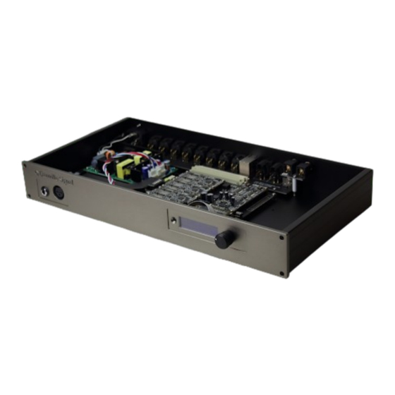
Page 7: Hardware
Hardware The dspNexus 2/8 is powered by an Analog Devices’ SHARC floating point DSP as implemented on a Danville dspblok DSP module. There are a number of pin compatible dspbloks that will work with the dspNexus. These choices will be discussed later in this manual. -
Page 8: Motherboard
The right data at the wrong time is the wrong data! The dspNexus 2/8 uses a very low phase jitter clock with very careful routing to minimize reflections to each device. The SHARC DSP has eight ASRCs that provide jitter attenuation far better than a low noise PLL is capable of achieving. - Page 9 In the dspNexus design, the SHARC DSP is the master processor. All other devices including the display microcontroller are subservient to the SHARC once the dspNexus is fully powered. The exception to this is when the dspNexus is in Sleep Mode. In this case, the SHARC and almost everything else is powered down with the exception of the display microcontroller.
- Page 10 Some customers are going to need to interface with single ended (unbalanced) sources (RCA phono). This can be done in two ways, the “OK” way and the better way. In both cases, you want the center HOT of the phono to connect to pin 2 (HOT) of the XLR connector. Ground of the phono connects to both pin 3 (COLD) and pin 1 (GND) of XLR.
-
Page 11: Microphone Inputs
Microphone Inputs There are two ways to connect microphones. If you have a +48V phantom microphone, you should use the front panel XLR. This actually uses another ADC located on the motherboard and disconnects the ADC module. The alternative is to use an external microphone / preamplifier combination. This may or may not have gain. - Page 12 Moving Magnet (MM): Some MM cartridges benefit from capacitive loading. This causes the resonance of the cartridge to fall which tends to boost the frequency response below the resonant frequency, mostly in the 10 to 20 kHz region. Some manufacturers rely on this effect. The inductance of the phono cartridge factors into the exact resonant frequency.
- Page 13 Connecting your turntable Your phono cartridge is essentially just a coil. In most cases, the shield of an RCA Phono is isolated from the turntable chassis. You want to use a cable with a twisted pair for the cartridge, and a shield for GND. Connect the Phono center pin to XLR Pin 2 (HOT), Phono GND to XLR Pin 3 (COLD) and the turntable chassis ground to XLR Pin 1 (GND).
-
Page 14: Dac Modules (Analog Outputs)
DAC Modules (Analog Outputs) The dspNexus analog outputs are balanced and uses a standard male XLR connector. Each DAC has individual 3dB analog attenuators. The full scale range of the DAC should ideally correspond to the maximum voltage swing you want from your amplifier. This will maximize signal/noise of the DAC. With woofers, this is often the maximum power of the amplifier, but sometimes you may want to restrict the level below full scale. -
Page 15: Headphone Amplifier
The dspNexus 2/8 convention with is to use channels 1-4 for the right speaker and channels 5-8 for the left speaker, starting with the highest frequencies in the lowest channel. Here is a 3 way example with optional subwoofers: Ch 1... -
Page 16: Display, Remote & Encoder
The IEC power entry has a power switch. This cuts all power to the dspNexus. Most of the time, power is managed via the front panel controls. In this case, the unit will be either fully operational or in a low power sleep mode. -
Page 17: Software
Software The dspNexus comes pre-installed with DSP Concepts' Audio Weaver. Danville has a licensing agreement that allows you to design your DSP crossover without buying additional tools or licensing. All you need is a Windows computer. In many cases, an optimized crossover may already have been designed by your speaker manufacturer. If this is your situation, you can safely ignore this section. - Page 18 The above design called an Audio Weaver canvas illustrates a typical crossover design for a one input, four output system. This one uses second order IIR filters. FIR type filters are also available. If you double click on a module, an inspector box opens up. In the example, we opened three inspectors. Inspectors allow you to adjust parameters for each module.
-
Page 19: Installation
Installation There are a few basics that almost all dspNexus systems are going to need to consider. You are likely to have many power amplifiers and you are probably going to connect to an external computer. This section addresses these issues. Since the dspNexus is likely implementing a DSP crossover it is very important that amplifier assignments are implemented so that tweeters do not see low frequency, high power content. -
Page 20: Input Connections
The dspNexus is capable of driving professional audio levels which is usually too hot for most power amplifiers. In general, you want the maximum level of the DAC is be near the full scale voltage of the mating power amplifier. This will maximize the available signal to noise and headroom of the system. The DACs have internal 3dB attenuators and additional 0.25dB steps to optimize these settings. -
Page 21: Control: Operation
Control: Operation While it is possible to run the dspNexus from a computer using Audio Weaver, this section is going to assume that you have a crossover designed and operating already and that you are now using the dspNexus as a control center. In this case, you will be using either the Remote or the front panel Encoder. The Encoder is located next to the display. -
Page 22: Splash
There are three main modes and one temporary mode (Splash) when using the Encoder: Splash / Sleep Volume Source Selection Settings This reduces to two main modes and the Splash screen when using the Remote. Splash / Sleep ... -
Page 23: Source Selection
Rotating the encoder changes the volume for the selected source. Alternatively, you can use the Up or Down on the Remote. Doubleclicking the encoder or pressing the Pause button of the remote causes the system to mute or unmute for all sources. When the system is muted, it is shown on the display. Example Screens: If the headphone is plugged in, the signal routing will mute the outputs on the back panel. - Page 24 Encoder Source Selection The Encoder needs to switch contexts, you press the Encoder knob quickly (like a computer single click mouse). This will change the display screen to Source Selection. Source Selection Screens: Rotating the knob will scroll through the available sources. Press the Encoder knob again will toggle back to the Volume Mode of the display Return back to Volume Screen: Source Variations...
- Page 25 Analog (Phono) The Analog inputs are balanced with Gain, Polarity and Equalization (EQ) configured in Setup. If the EQ is set to Flat, the displayed name is Analog. If the EQ is set to RIAA, the name is changed to Phono. Usually, you will just want to listen in a standard stereo configuration.
- Page 26 Bluetooth APTx-HD Bluetooth Audio is available for convenience. Perhaps your friend has a song on a phone that he or she wants to share. Bluetooth has a variety of profiles. Phones are fairly universal with A2DP support. This is about MP3 quality. Some phones also support APTx-HD. This profile has near CD quality performance. Phantom Powered Microphone There is an XLR connector on the front panel for phantom powered microphones.
-
Page 27: Control: Setup - General
Control: Setup – General The dspNexus 2/8 Settings Mode is infrequently accessed and the most complex of the control functions. Its main purpose is to allow you to configure the dspNexus optimally for the environment where it is expected to operate. It still works under the principle that there is a working signal processing design that is implementing a crossover, but that there are still. - Page 28 Remote Functions The Remote functions are as follows: The Up and Down Arrows increase/decrease values The Left and Right Arrows rotate through the selections. Center functions like an Enter Key. The Pause Button is ignored Menu moves up one menu level.
-
Page 29: Control: Setup - Measurement & Room Eq
Control: Setup – Measurement & Room EQ The dspNexus 2/8 Measurement and Room EQ functions are used with a measurement microphone in conjunction with an external speaker design tool such as Room EQ Wizard. The are two methods that are available: Measurement and Room EQ. -
Page 30: Control: Setup - Active Sources
Control: Setup – Active Sources Active Sources determines which Sources will be selectable during normal operation. For many users, this pares down the choices to the subset that they actually care about. Upon entry into the Active Source Menu, the first source is displayed and its current setting. Press the Center button (Enter) on the Remote or the knob on the Encoder if you want to change states (On or Off). -
Page 31: S/Pdif
S/PDIF S/PDIF has a Normal and Inverted option. Unless, you are using a TV as an input source, we suggest that you use USB when using an external computer or music server. Bluetooth aptX-HD S/PDIF has a Normal and Inverted option. Unless, you are using a TV as an input source, we suggest that you use USB from an external computer or music server. -
Page 32: Control: Setup - Adc Settings
Control: Setup – ADC Settings The ADC Settings tailor the input source requirements to best take advantage of the wide dynamic range of the ADC Module. ADC Level The ADC has programmable gain amplifiers (PGAs) that accommodate a large range of audio analog sources from professional audio levels to the high gain requirements of phono preamplifiers or microphones. -
Page 33: Control: Setup - Dac Settings
Control: Setup – DAC Settings The DACs have individual programmable attenuators that accommodate the broad range of amplifier sensitivities. The maximum output level can also be set to support+4 dBu professional line out requirements. Amplifier Considerations Power amplifiers may have balanced or unbalanced inputs. If you have both options available, use the balanced inputs. -
Page 34: Subwoofer Considerations
Subwoofer Considerations If you have subwoofers that are located independently from your mains, you have a few parameters that are important to adjust. In the general situation, the location of the subwoofers is unknown with respect to the mains when the crossover is created. It is room dependent. You want to time align the subwoofer to the mains. - Page 35 Second Setting DAC Level 1-8 Screen: After an Enter, this now points to the Level. Using the Left or Right Arrow changes the level. The image assumes that you changed the level. Next Setting DAC Level 1-8 Screen: After an Enter, this now points back to the Level. Using the Left or Right Arrow changes the level. Next Setting DAC Level 1-8 Screen: The image assumes that you changed the channel.
-
Page 36: Dac Delay Units
DAC Delay Units Delay units can be calculated in meters, feet or milliseconds. Room temperature is assumed for distance conversions. The actual delay is converted internally to number of sample delays: (1/192000) ~ 5us increments. DAC Delay All Delay units can be calculated in meters, feet or milliseconds. Room temperature is assumed and the actual delay is converted in internal units of number of sample delays (1/192000) ~ 5us. -
Page 37: Polarity All
Next Setting DAC Delay 1-8 Screen: The image assumes that you changed the channel. The delay reflects the current value for channel 2 Later Setting DAC Delay 1-8 Screen: Two steps: Entered to point to delay and then changed the delay value. Last Setting DAC Delay 1-8 Screen: If you go past the last channel you arrive at the Exit option, Pressing Menu will also exit. -
Page 38: Control: Setup - Line Out Settings
Control: Setup – Line Out Settings In the dspNexus, we generally think of the outputs as being the eight balanced analog outputs driven by the DACs. There are other outputs available as well. These are stereo and tend to be used outside of the typical crossover features. -
Page 39: Bluetooth Out
Sample Rate 48k, 96k, 192k Bluetooth Out Level You can set up the line output level of the USB in 32 steps of 0.5dB. Track Volume If the Track Volume is On, the level will scale with the Volume setting, otherwise the output is fixed. dspNexus™... -
Page 40: Control: Setup - Frequency Response
Control: Setup – Frequency Response Audio Weaver can be set up to include a pair of low frequency and high frequency shelf filters. The idea is that some users may want simple tailoring of the frequency response after a crossover has been designed. In many cases, this function may not be implemented in the crossover and therefore these settings will be ignored. -
Page 41: Control: Setup - Info
DAC1, DAC2, DAC3, DAC4 AK4493 or AK4499 This is the DAC converter used for each Analog Output Module. DSP Module dspblok 21569uac2 or dspblok 21469uac2 This is the DSP Module used in the dspNexus 2/8. dspNexus™ 2/8 User Manual Page 37... -
Page 42: Product Warranty
If Danville Signal Processing receives notice of such defects during the warranty period, Danville Signal Processing shall, at its option, either repair or replace software media or firmware, which do not execute their programming instructions due to such defects.
Need help?
Do you have a question about the dspNexus 2/8 and is the answer not in the manual?
Questions and answers