Advertisement
Quick Links
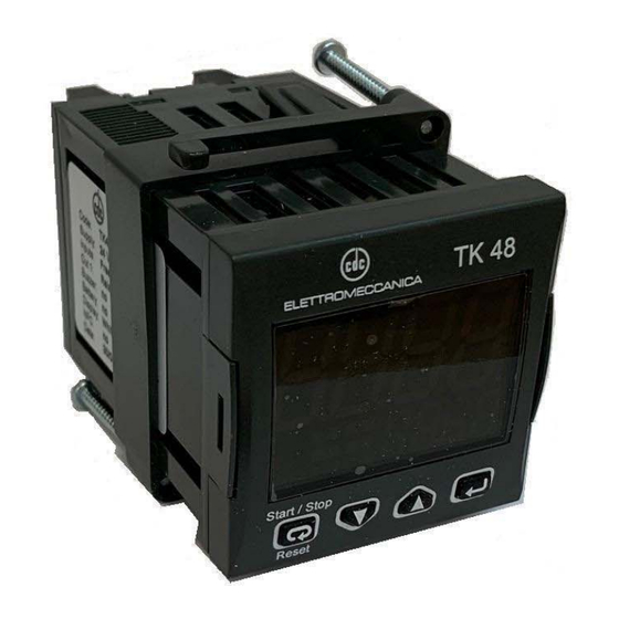
TK 48
TIMER/PULSE COUNTER/
DIGITAL ELECTRONIC
POWER LIMITER
Elettromeccanica CDC S.r.l
Via Treviglio 56/58 24053
Brignano Gera D'Adda (Bg)
TEL.: +39 0363 382155
FAX: +39 0363 382099
www.cdcelettromeccanica.it
vendite@cdcelettromeccanica.it
PREFACE
D
This manual contains the information necessary for
the product to be installed correctly and also instruc-
tions for its maintenance and use; we therefore recom-
mend that the utmost attention is paid to the following
instructions and to save it.
Elettromeccanica CDC S.r.l. reserves the right to make any
formal or functional changes at any moment and without any
notice. Elettromeccanica CDC S.r.l. and its legal
representatives do not assume any responsibility for any
damage to people, things or animals deriving from violation,
wrong or improper use or in any case not in compliance with
the instrument features.
D
Whenever a failure or a malfunction of the device may
cause dangerous situations for persons, thing or animals,
please remember that the plant has to be equipped with
additional devices which will guarantee safety.
ELETTROMECCANICA CDC - TK48 - MANUAL REV.2 - PAG.1
Index
1. Instrument description ............................................... 1
1.1
General description ........................................................... 1
1.2
Front panel description ..................................................... 2
2. Programming ............................................................... 2
2.1
Set Points (timings) programming ..................................... 2
2.2
Standard mode parameters setting ................................... 2
2.3
Parameter protection using a password ............................ 3
2.4
Customized mode parameter programming
(parameters programming level) ......................................... 3
2.5
Reset parameters to default value .................................... 3
2.6
Keyboard lock function ...................................................... 3
3. Usage warnings ........................................................... 3
3.1
Allowed Usage .................................................................. 3
4. Installation warnings ................................................... 4
4.1
Mechanical Mounting ........................................................ 4
4.2
Electrical connections ....................................................... 4
5. Operating mode ........................................................... 5
5.1
Operation selection as:
Timer, Pulse counter or Power limiter ............................... 5
5.2
Operation as a timer ......................................................... 5
5.3
Operation as a Pulse counter ........................................... 9
5.4
Operation as a Power limiter ........................................... 10
6.
Programmable parameters table .............................. 12
7.
Problems and maintenance ...................................... 15
7.1
Cleaning ..........................................................................15
7.2
Disposal ..........................................................................15
8.
Warranty and repairs ................................................. 15
9.
Technical data ............................................................ 15
9.1 Electrical data .................................................................15
9.2 Mechanical characteristics ..............................................15
9.3 Functional features .........................................................15
How to order .............................................................. 16
10.
1. INSTRUMENT DESCRIPTION
1.1
General description
TK48 is a microprocessor based digital timer/pulse coun-
ter/power limiter.
The instrument used as a timer offers the possibility to
program: up to 3 timings (Set point), 6 operating modes for
OUT1 output, 10 operating modes for OUT2 output, 4 time
scales (which allow a count from a maximum of 9999 hours
to a minimum of 0.01 seconds), 6 counting enabling func-
tioning modes and 2 counting modes (UP or DOWN).
The instrument used as a pulse counter offers the pos-
sibility to program: up to 2 Set points, 3 operating modes
for OUT1 output, 4 operating modes for OUT2 output and
offers the possibility of counting division.
Moreover, the instrument can also be used as a power
limiter by programming a duty-cycle from 0 ÷ 100% and a
total cycle time from 1 ÷ 900 s.
The upper 4-digit display normally shows the counting
status while the lower 4-digit display the selected timing
(set-point), the status of the outputs is shown by 2 LEDs.
The instrument has 1 counting/counting enabling input
(CNT) and 1 digital input with programmable operation
(RESET or reverse counting) whose signals can come from
free of voltage contacts, from devices with NPN or PNP
transistor output. It can have up to 2 relay outputs or for
driving Solid State Relays (SSR).
Advertisement

Related Manuals for CDC Elettromeccanica TK 48

Summary of Contents for CDC Elettromeccanica TK 48
- Page 1 Index TK 48 1. Instrument description ..........1 General description ............1 Front panel description ............. 2 2. Programming ............... 2 Set Points (timings) programming ........2 TIMER/PULSE COUNTER/ Standard mode parameters setting ........2 Parameter protection using a password ......3...
- Page 2 2. PROGRAMMING The instrument can be equipped with an internal or exter- nal buzzer (connected to the Out2 output) to signal the Set Points (timings) programming counting end. The instrument programming can be done through 3 front The normal programming mode of the delay times (Set keys where there is also the programmable key for the Times) occurs by pressing and releasing the...
- Page 3 word (protected). If SET LED is steady ON the parameter keys. Once the desired value has been set, press the is programmable without password (unprotected). again: the new value is stored and the upper display – To change the parameter visibility, press the shows only the code of the modified parameter.
- Page 4 The instrument must not be used in dangerous environ- Mounting brackets ments (flammable or explosive) without adequate protections. The installer must ensure that the EMC rules are respected, also after the instrument installation, if necessary using proper filters. 4. INSTALLATION WARNINGS Mechanical Mounting Panel + Gasket Type 2...
- Page 5 4.2.2 L-type CNT input connection to devices when it is activated and also has priority over the other com- mands (while RST is active, the count cannot start). with transistor output The counting Start signal can therefore be given by the -Start/Stop key, which normally has bistable (toggle) operation, or via the CNT count enable digital input.
- Page 6 F. o 1t = 2 count stops disabling the output if active. This operating mode is similar to the one of the tradition- S.t1 Start al timers in which counting is enabled when the instru- OUT1 ment is powered while the Reset occurs when power Reset supply is removed.
- Page 7 5.2.4 Out2 Operating mode when set as Timer F. o 2t = 4 - Out2 works as Out1 (with s. t 1 time) but with a relative s. t 3 time in advance The Output 2 operation can be programmed in 10 different modes with F.
- Page 8 F. o 2t = 10 - Symmetrical denied operation with respect F. o 1t = 2, F. o 2t = 6 to Out1 with dead time S. t 3 Start S.t1 S.t3 S.t2 As in F. o 2t = 9 mode, while counting Out2 output is OUT1 activated with the opposite logic to Out1, with an S.
- Page 9 Operation as a Pulse counter input frequency signal is low. i. f rC = 2 5.3.1 Counter display operation LED is used to indicate: INPUT – Count in progress (steady on); – Count enderd and Reset status (OFF). INPUT (i. f rC = 2) In particular, the count is considered in progress at the fi st impulse acquired after the Reset.
- Page 10 5.3.5 Internal buzzer operation when set as Counter f. o 1C = 3 (Count) The internal buzzer can be programmed using the F. b uC parameter to operate in the following ways: INPUT S.C1 S.C1 oF Internal buzzer disabled; Out1 Activated at the end of count for S.
- Page 11 and activated for the time: [S. t c - (S. t c x P/100)]; F. o 1P = 2 - Start OFF When the operation is turned ON, Out1 remains not ac- tive for the time calculated based on the cycle time and the power set and then it is activated until the cycle time expires and so on until the operation is turned OFF.
- Page 12 6. PROGRAMMABLE PARAMETERS TABLE Here below is a description of all the parameters available on the instrument. Some of them may not be present, either due to the fact they depend on the type of instrument or because they are automatically disabled as unnecessary. The Hexadeci- mal address is used by the serial communicatione.
- Page 13 Hex. Parameter Description Range Default Note address 1 Resets the current count; 2 Stops the current count storing the value reached; 2818 Backup operation mode 3 Stores the reached value and when the power returns, it restarts F. b ut from that value if the conditions for restarting are present;...
- Page 14 Parameters available in POWER LIMITER mode Hex. Parameter Description Range Default Note address S. S P 2844 Output power of the power limiter 0 ÷ 100 S. t c 2845 Cycle time of the power limiter 1 ÷ 900 s 1 Start ON;...
- Page 15 10. ORDER CODE 9. TECHNICAL DATA Electrical data TK48 1 X I M UU YY G Power supply: 24 VAC/VDC, 100 ÷ 240 VAC ±10%; Contact input AC frequency: 50/60 Hz; Voltage input Power consumption: About 3 VA; Inputs: 2 digital inputs CNT (counting enable) and RST With buzzer Not buzzer (reset) for voltage free contacts, or in voltage (the same as...
Need help?
Do you have a question about the TK 48 and is the answer not in the manual?
Questions and answers