Table of Contents
Advertisement
Quick Links
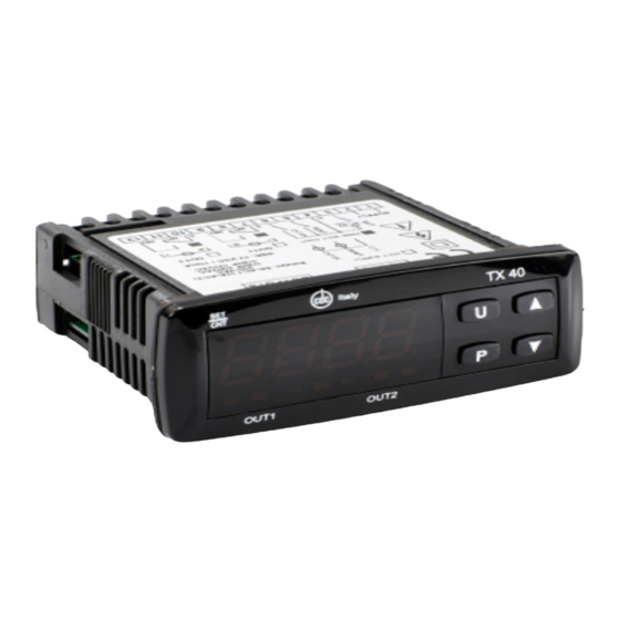
TX40
DIGITAL ELECTRONIC
MICROPROCESSOR
TIMER
MANUAL rev.2 11/2021
ELETTROMECCANICA CDC S.r.l
VIA TREVIGLIO 56/58
BRIGNANO GERA D'ADDA (BG)
TEL. +39 0363 382155
FAX +39 0363 382099
www.cdcelettromeccanica.it
vendite@cdcelettromeccanica.it
PREFACE
D
D
This manual contains the information necessary for
the product to be installed correctly and also instruc-
tions for its maintenance and use; we therefore recom-
mend that the utmost attention is paid to the following
instructions and to save it.
This document is the exclusive property of Elettromeccanica
CDC S.r.l. which forbids any reproduction and divulgation,
even partially, of the document, unless expressly authorized.
Elettromeccanica CDC S.r.l. reserves the right to make any
formal or functional changes at any moment and without any
notice. Elettromeccanica CDC S.r.l. and its legal
representatives do not assume any responsibility for any
damage to people, things or animals deriving from violation,
wrong or improper use or in any case not in compliance with
the instrument features.
D
D
Whenever a failure or a malfunction of the device may
cause dangerous situations for persons, thing or animals,
please remember that the plant has to be equipped with
additional devices which will guarantee safety.
ELETTROMECCANICA CDC S.r.l - TX40 - MANUAL rev.2 - PAG.1
Index
1. Instrument description ............................................... 1
1.1
General description ........................................................... 1
1.2
Front panel description ..................................................... 2
2. Programming ............................................................... 2
2.1
Fast Set Times programming ............................................ 2
2.2
Standard mode parameters programming ........................ 2
2.3
Parameter protection using a password ............................ 3
2.4
(parameters programming level) ......................................... 3
2.5
Reset parameters to default value .................................... 3
2.6
Keyboard lock function ...................................................... 3
3. Usage warnings ........................................................... 4
3.1
Allowed Usage .................................................................. 4
4. Installation warnings ................................................... 4
4.1
Mechanical Mounting ........................................................ 4
4.2
Mechanical Dimensions [mm] ........................................... 4
4.2.1
Instrument dimensions ......................................................... 4
4.2.2
Panel cutout .......................................................................... 4
4.2.3
Mounting brackets ................................................................ 4
4.3
Electrical connections ....................................................... 4
4.3.1
Electrical connection diagram ............................................... 5
5. Operating mode ........................................................... 5
5.1
Display operation .............................................................. 5
5.2
Operation of the Counting commands .............................. 5
5.3
OUT1 Operating mode ...................................................... 6
5.4
OUT2 Operating mode ...................................................... 7
5.5
Internal buzzer operation .................................................. 8
5.6
Operation in case of power supply failure (backup) .......... 8
6. Accessories ................................................................. 9
6.1
Parameters configuration with A01 ................................... 9
6.2
Parameters configuration with AFC1 ................................ 9
7. Programmable parameters table .............................. 10
8. Problems and maintenance ...................................... 11
8.1
Cleaning .......................................................................... 11
8.2
Disposal .......................................................................... 11
9. Warranty and repairs ................................................. 11
10. Technical data ............................................................ 11
10.1 Electrical data ................................................................. 11
10.2 Mechanical characteristics .............................................. 11
10.3 Functional features ......................................................... 11
11. How to order .............................................................. 12
1. INSTRUMENT DESCRIPTION
1.1
General description
TX40 is a digital microprocessor timer, it offers the possibility
to program: up to 3 delay times (or Set Times), 5 operating
modes for OUT1 output, 5 operating modes for OUT2 output,
4 time scales (allowing timings from 9999 hours max. to 0.01
s min.), 6 counting start modes and 2 counting modes (UP
or DOWN). The timer can also be equipped with an internal
or external buzzer for signaling the end of the count.
The 4 digits display normally shows the counting status
while the outputs status is signalled by 2 LEDs. The instru-
ment has also 2 digital inputs for voltage-free contacts that
can be used for the count enabling (CNT EN) and Reset
(RES) commands and can have up to 2 relay outputs or
SSR for driving Solid State Relays.
The instrument is programmed by using the 3 of the front
panel keys while the counting commands can be submitted
-Start/Stop or through the digital inputs CNT
using the
EN and RES. The operating parameters configuration can
be done through keypad, A01 device connected to TTL port
(standard) or using NFC communication (optional).
Advertisement
Table of Contents

Related Manuals for CDC Elettromeccanica TX40

Summary of Contents for CDC Elettromeccanica TX40
-
Page 1: Table Of Contents
This manual contains the information necessary for the product to be installed correctly and also instruc- TX40 is a digital microprocessor timer, it offers the possibility tions for its maintenance and use; we therefore recom- to program: up to 3 delay times (or Set Times), 5 operating... -
Page 2: Front Panel Description
2. Only s. t 2 Set Time value can be set with this procedure; 3. s. t 1 and s. t 2 Set Times can be set with this procedure; ELETTROMECCANICA CDC S.r.l - TX40 - MANUAL rev.2 - PAG.2... -
Page 3: Parameter Protection Using A Password
In case some parameters are set as Not protected, access- ing the programming mode the display first shows the Not protected parameters, then the r. p parameter through which will be possible to access also the protected parameters. ELETTROMECCANICA CDC S.r.l - TX40 - MANUAL rev.2 - PAG.3... -
Page 4: Usage Warnings
Connect the instrument as far away as possible from sourc- es of electromagnetic disturbances such as motors, power relays, relays, solenoid valves, etc.. Recommended panel cutout 4.2.3 Mounting brackets “Butterfly” type brackets “Screw type” bracket ELETTROMECCANICA CDC S.r.l - TX40 - MANUAL rev.2 - PAG.4... -
Page 5: Electrical Connections
RESET 0 . 1 . 2 . 3 . 4 . 5 . 6 . 7 . 8 . 0 Count Start Stop Start Stop/ Reset ELETTROMECCANICA CDC S.r.l - TX40 - MANUAL rev.2 - PAG.5... -
Page 6: Out1 Operating Mode
In this mode, the front -Start/Stop button (if t. U Ft = 2) acts in exactly the same way as the CNT input. ELETTROMECCANICA CDC S.r.l - TX40 - MANUAL rev.2 - PAG.6... -
Page 7: Out2 Operating Mode
1t = 4, f. o 2t = 3 OUT2 output operates exactly like OUT1 output in order to have a double output contact. S.t1 S.t2 S.t1 S.t2 Start OUT1 S.t3 S.t3 OUT2 Reset ELETTROMECCANICA CDC S.r.l - TX40 - MANUAL rev.2 - PAG.7... -
Page 8: Internal Buzzer Operation
S.t3 S.t3 OUT2 Reset f. o 1t = 4, f. o 2t = 4 S.t1 S.t2 S.t1 S.t2 Start OUT1 S.t3 S.t3 OUT2 Reset ELETTROMECCANICA CDC S.r.l - TX40 - MANUAL rev.2 - PAG.8... -
Page 9: Programmable Parameters Table
Lock disabled; Keyboard lock t. L o 1 ÷ 9999 s oF Password disabled; Password parameters protection t. P P 1 ÷ 9999 ELETTROMECCANICA CDC S.r.l - TX40 - MANUAL rev.2 - PAG.9... -
Page 10: Problems And Maintenance
H or L type power supply and inputs when a relay + SSR drive output combination is present; No insulation between type F power supply terminals and input. ELETTROMECCANICA CDC S.r.l - TX40 - MANUAL rev.2 - PAG.10... - Page 11 T X 4 0 H I R R 1 0 Y Y P Morsettiera estraibile / Removable screw terminal Faston / Faston Terminali a vite / Screw terminal Buzzer / With buzzer No buzzer / Not buzzer Relè Relay Statica/ Static ELETTROMECCANICA CDC S.r.l - TX40 - MANUAL rev.2 - PAG.11...
Need help?
Do you have a question about the TX40 and is the answer not in the manual?
Questions and answers