Advertisement
Quick Links
Instruction
Manual
Instrument Model Number_____________________________
Instrument Serial Number _________________________________
Anderson Instrument Co. Inc.
156 Auriesville Road
Fultonville, NY 12072
1-800-833-0081
Fax 518-922-8997
www.andinst.com
Form Number AIC3410
© October 1997
Rev. November 2004
Advertisement

Related Manuals for Anderson JD Series

Summary of Contents for Anderson JD Series
- Page 1 Anderson Instrument Co. Inc. Instruction 156 Auriesville Road Fultonville, NY 12072 1-800-833-0081 Fax 518-922-8997 Manual www.andinst.com Instrument Model Number_____________________________ Instrument Serial Number _________________________________ Form Number AIC3410 © October 1997 Rev. November 2004...
-
Page 2: Table Of Contents
Table of Contents Section 1 - General Page 1.1 DESCRIPTION 1.2 SPECIFICATIONS 1.3 TYPICAL SYSTEM APPLICATION Section 2 - Installation 2.1 PRESSURE SENSOR LOCATION 2.2 INSTRUMENT CASE 2.3 ELECTRICAL WIRING 2.3.1 Interconnection With Other HTST Components 2.3.2 Power Supply 2.3.3 Booster Pump Switch 2.3.4 Input Signal Connections 2.3.5 Transmitter Signal Connections 2.3.6 4-20 mA Output Wiring... -
Page 3: Section 1 General
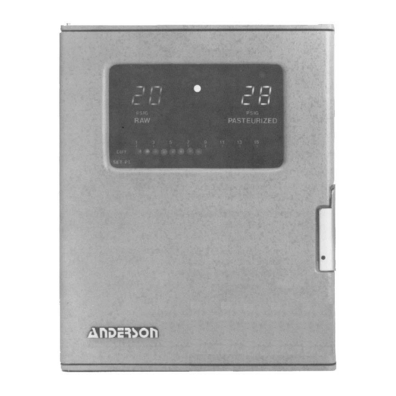
1.1 DESCRIPTION 1.1 DESCRIPTION The JD series Differential Pressure Switch is an all-electronic, solid-state instrument that complies with all applicable USPH codes. The instrument senses raw and pasteurized product pressures and displays them in bright 1/2" LED numerals. The differential is calcu- lated and displayed on the bargraph as is the adjustable setpoint. -
Page 4: Specifications
1.2 SPECIFICATIONS (Differential Pressure Switch Only) 1.2 SPECIFICATIONS (Differential Pressure Switch Only) 1.2 SPECIFICATIONS (Differential Pressure Switch Only) 1.2 SPECIFICATIONS (Differential Pressure Switch Only) 1.2 SPECIFICATIONS (Differential Pressure Switch Only) Process Pressure Range: -10 to +99 psig standard (-10 to +199 psig, 0-9.9 Bar, 0-19.9 Bar optional) Accuracy*: ±... -
Page 5: Section 2 Installation
FIGURE 2 TYPICAL HTST PASTEURIZATION SYSTEM FIGURE 2 TYPICAL HTST PASTEURIZATION SYSTEM FIGURE 2 TYPICAL HTST PASTEURIZATION SYSTEM FIGURE 2 TYPICAL HTST PASTEURIZATION SYSTEM FIGURE 2 TYPICAL HTST PASTEURIZATION SYSTEM TYPICAL HTST PROCESS AV-9900 HTST DART Reference JD Differential Recorder Thermometer Pressure Switch 801 Loop Controller... -
Page 6: Instrument Case
2.2 INSTRUMENT CASE 2.2 INSTRUMENT CASE 2.2 INSTRUMENT CASE 2.2 INSTRUMENT CASE 2.2 INSTRUMENT CASE 2.2.1 Location Select a location for the instrument which is accessible, clean and free from exces- sive vibrations as well as from wide variations in temperature. The instrument should be mounted vertically on a rigid support or in a panel. -
Page 7: Electrical Wiring
2.3 ELECTRICAL WIRING 2.3 ELECTRICAL WIRING 2.3 ELECTRICAL WIRING 2.3 ELECTRICAL WIRING 2.3 ELECTRICAL WIRING 2.3.1 Interconnection with other HTST Components A functional representation of the HTST Differential Pressure Switch, as intercon- nected with other components of the HTST process is shown in Figure 5. The connec- tion terminal numbering of 1-5 (shown) corresponds to general industry numbering standards. -
Page 8: Power Supply
2.3.2 Power Supply The HTST is powered by either 120 or 240 VAC, 50-60Hz. WARNING: Check the instrument nameplate for the specific rating before connecting to power source. Current draw is less than 1/4 amp, so 18 AWG, 2-conductor with ground instrument wire is sufficient. -
Page 9: Input Signal Connections
FIGURE 7 HTST DIFFERENTIAL PRESSURE SWITCH WIRING with OPTIONAL HP LIMIT FIGURE 7 HTST DIFFERENTIAL PRESSURE SWITCH WIRING with OPTIONAL HP LIMIT FIGURE 7 HTST DIFFERENTIAL PRESSURE SWITCH WIRING with OPTIONAL HP LIMIT FIGURE 7 HTST DIFFERENTIAL PRESSURE SWITCH WIRING with OPTIONAL HP LIMIT FIGURE 7 HTST DIFFERENTIAL PRESSURE SWITCH WIRING with OPTIONAL HP LIMIT SWITCH SWITCH... -
Page 10: Transmitter Signal Connections
2.3.5 Transmitter Signal Connections The Instrument is shipped with sensors pre-wired and calibrated. In the event that the wires are removed for installation, they should be re-attached as shown below. Access to the terminal blocks is gained by removal of the two right side thumbscrews on the display board, and pivoting the board away. -
Page 11: Ma Output Wiring
2.3.6 4-20 mA Output Wiring If utilizing the 4-20 mA retransmission outputs, they can be wired as shown below. NOTE: These inputs are non-isolated and cannot be wired with one leg grounded as in some programmable controllers designed for single ended inputs. NOTE: If interface boards are to be removed to facilitate wiring, turn power off before pulling boards. -
Page 12: Adjustment Of Differential Pressure Set Point
3.2 ADJUSTMENT OF DIFFERENTIAL PRESSURE SET POINT 3.2 ADJUSTMENT OF DIFFERENTIAL PRESSURE SET POINT 3.2 ADJUSTMENT OF DIFFERENTIAL PRESSURE SET POINT 3.2 ADJUSTMENT OF DIFFERENTIAL PRESSURE SET POINT 3.2 ADJUSTMENT OF DIFFERENTIAL PRESSURE SET POINT In order to adjust the low limit set point of the differential pressure switch, the case door must be opened, thereby requiring the breaking of the seal attached to the door by the local health authority. -
Page 13: High Pressure Limit Switch
FIGURE 11 DISPLAY CIRCUITRY AND ADJUSTMENTS (DOOR OPEN) FIGURE 11 DISPLAY CIRCUITRY AND ADJUSTMENTS (DOOR OPEN) FIGURE 11 DISPLAY CIRCUITRY AND ADJUSTMENTS (DOOR OPEN) FIGURE 11 DISPLAY CIRCUITRY AND ADJUSTMENTS (DOOR OPEN) FIGURE 11 DISPLAY CIRCUITRY AND ADJUSTMENTS (DOOR OPEN) "... -
Page 14: Section 4 Test And Calibration
Section 4 Test and Calibration 4.1 TEST PROCEDURES 4.1 TEST PROCEDURES 4.1 TEST PROCEDURES 4.1 TEST PROCEDURES 4.1 TEST PROCEDURES This test procedure is written only as a guideline and is not intended to replace the test procedure in the USPH, Pasteurized Milk Ordinance. The test is designed to check the accuracy of both sensors, accuracy of the differential indicator, and operation of the differen- tial switch and relay. -
Page 15: Calibration Adjustments
Procedure Checking Pressure Readings at Zero: Loosen the process connection at both pressure sensors and allow any fluid to drain through the loose connections. Both the raw and pasteurized digital displays should read zero. To adjust, open the instrument cover and turn the blue potentiometer ("pot") labeled "o"... - Page 16 FIGURE 13 CALIBRATION ADJUSTMENT LOCATIONS FIGURE 13 CALIBRATION ADJUSTMENT LOCATIONS FIGURE 13 CALIBRATION ADJUSTMENT LOCATIONS FIGURE 13 CALIBRATION ADJUSTMENT LOCATIONS FIGURE 13 CALIBRATION ADJUSTMENT LOCATIONS High Pressure K1 Relay Setpoint Adjust Open/Closed High Pressure Differential Bargraph Adjust Setpoint Adjust High Pressure Relay State Past Display Raw Display...
-
Page 17: Calibration Procedure
4.3 CALIBRATION PROCEDURE 4.3 CALIBRATION PROCEDURE 4.3 CALIBRATION PROCEDURE 4.3 CALIBRATION PROCEDURE 4.3 CALIBRATION PROCEDURE Taking care not to dent the sensor diaphragms, remove the sensors from the process and connect to the test fixture. Locate the 0-1 VDC test points B, C & D as shown in Figure 13. Connect the Black (-) meter lead to TP C, and the Red (+) meter to TP B. -
Page 18: Section 5 - Troubleshooting
The formula for determining proper output at any known pressure or differential is: Differential Zero and Span adjustments for these outputs are located as shown in Figure 9. Zero for the output should be adjusted during the final zero check in Section 4.3 and span during the final span check in 4.3. - Page 19 Significant Error in Pressure Readings Cause: Loose or improperly inserted interface boards Caution: Never remove or reinsert interface boards with power "on". Turn off power or remove fuse. Action: Open case door and push interface boards firmly into slide socket (see Figure 13).
- Page 20 Several voltage (D.C.) checks can be easily made to determine sensor and circuit board functioning. Checks are first made at the input terminal block to check excitation voltage and sensor outputs. These are followed by display board voltage checks to verify interface card functioning and calibration.
-
Page 21: Ac Power Connections
Appendix A FUSE(S) AC POWER CONNECTIONS... -
Page 22: Master Parts List
Appendix B MASTER PARTS LIST MASTER PARTS LIST MASTER PARTS LIST MASTER PARTS LIST MASTER PARTS LIST Unit Part Number Part Description JD (Man) 56014E0098 1-15 PSID Display Board JD (Man) 56014E00097 Powerboard / 120VAC JD (Man) SY070G0051100 Transducer / 2"TC / 0-99 / with Card JD (Man) SY070G0041100 Transducer / 1.5"TC / 0-99 / with Card... -
Page 23: Warranty And Return Statement
These products are warranted to be free from functional defects in materials and workman- ship at the time the products leave the Anderson factory and to conform at that time to the specifications set forth in the relevant Anderson instruction manual or manuals, sheet or sheets, for such products for a period of one year.
Need help?
Do you have a question about the JD Series and is the answer not in the manual?
Questions and answers