
Subscribe to Our Youtube Channel
Related Manuals for Maggi JUNIOR 640 CE


Summary of Contents for Maggi JUNIOR 640 CE
- Page 1 WOODWORKING MACHINERY MACHINE CODE 15407100 00008778 MANUAL CODE THIS MANUAL SHOULD BE KEPT FOR FUTURE REFERENCE AND SHOULD ALWAYS FOLLOW THE MACHINE JUNIOR 640 CE ORIGINAL USE and MAINTENANCE MANUAL...
- Page 2 Page intentionally left blank...
- Page 3 MAGGI TECHNOLOGY reserves the right to make changes to the product described in this manual at any time and without notice.
- Page 4 Page intentionally left blank...
- Page 5 Il costruttore Maggi Technology S.r.l. Via delle Regioni, 299 - 50052 Certaldo (FI) ITALIA Dichiara che la macchina La macchina RADIALE Modello JUNIOR 640 CE è conforme a tutte le disposizioni delle direttive: 2006/42/CE (Macchine) 2014/30/UE (Compatibilità Elettromagnetica) 2014/35/UE (Bassa tensione) e ne costituisce il fascicolo tecnico.
- Page 6 INDICE 1. INTRODUCTION ………………………………………………………………………………... 1.1 Definition of operator …………………………………………………………………… 1.1.1 Operator requirements …………………………………………………………………….. 1.1.2 Prohibitions for the operator 1.2 Obligation for the operator ……………………………………………………………………. 1.3 Importance of the manual …………………………………………………………………… 1.4 Regulatory references ………………………………………………………………………….. 1.5 Identification data of the manufacturer ……………………………………………………. 1.6 CE marking plate …………………………………………………………………………..
- Page 7 12.4 Connection to the suction system …………………………………………………… 12.5 square the arm with the serving rule …………………………………… 13 MOVEMENTS AND USE OF THE MACHINE 13.1 General recommendations for cutting operations ………………………………………… 13.2 Checking the safety devices ………………………………………………………… 13.3 Assembling the blade and blade guard 13.4 Workgroup Security Lockout ………………………………………………..
- Page 8 GENERAL INFORMATION CONCERNING THE MANUFACTURER Fabbricante: MAGGI TECHNOLOGY S.r.l. Indirizzo: Via delle Regioni, 299 - 50052 Città: CERTALDO (FI) Nazione: ITALIA Tel. +39 0571 63541 Fax. +39 0571 664275 E-mail: service@maggi-technology.com Web: maggi-technology.com 1. INTRODUCTION 1.1 DEFINITION OF OPERATOR According to what is written in Directive 98/37/EC of 23 July 1998 (implemented in Italy by Presidential Decree 459 of 24 July 1996), Annex I, Essential Safety Requirement 1.1.1, in this manual the term operator means:...
- Page 9 • immediately report to the employer and/or workers who have a specific function regarding the protection of the safety and health of workers any work situation which, for reasonable reasons, they believe could constitute a serious and immediate danger to safety and health, as well as any defects found in the protection systems;...
- Page 10 UNI EN 1050; 1996 - Safety of machinery - Principles for risk assessment. 1.5 MANUFACTURER'S IDENTIFICATION DATA The identification of the Company MAGGI TECHNOLOGY as the manufacturer of the machine takes place in accordance with the legislation in force by means of the documents listed below: •...
- Page 11 If for accidental reasons the "CE MARKING" plate is damaged, detached from the machine, or simply without the manufacturer's seal, the customer is obliged to inform MAGGI TECHNOLOGY and ask for its replacement. 1.7 TYPOGRAPHICAL AGREEMENTS Information referring to procedures or practices which, if not performed correctly, can cause injury, death or long-term risks to people's health and the environment.
- Page 12 The warranty for replaced or repaired parts expires on the same day of the expiry of the machine warranty. Furthermore, MAGGI TECHNOLOGY is not liable for lack of conformity of the machine caused by failure to observe the rules set out in the instruction manual and in any case by misuse or treatment of the machine.
- Page 13 2. GENERAL SAFETY WARNINGS 2.1 SAFETY STANDARDS • Carefully read the instruction manual for use and maintenance before proceeding with start-up, use, maintenance or any other operation on the machine. • Strictly comply with all the attention, danger and caution information contained in the manual and the safety signs applied directly to the machine.
- Page 14 − 2.3 DANGER SIGNS DANGER: Avoid contact with the gears and all those parts that could start moving. DANGER: Before carrying out any operation on the electrical circuit, make sure that the power supply is switched off. DANGER: Risk of crushing hands between moving mechanical parts. −...
- Page 15 45°. 3.2 APPLICABLE TOOLS MAGGI TECHNOLOGY recommends using blades suitable for the type of work to be carried out, and also that they ensure high reliability and a reduced risk of kickbacks and accidents: universal circular blades for longitudinal and transversal cuts with alternating teeth with chip limiter ( suitable for radial saws).
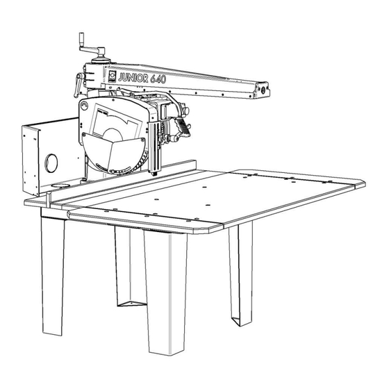
- Page 16 3.3 PARTS OF THE MACHINE 10-Rear suction hood 1-Frame 11-Bar rule 2-Work table 12-Arm positioning lever 3-Base 13-Arm rotation locking handle 4-Column 14-Arm lift handle 5-Arm 15-Blade tilt lever 6-Blade cover 16-Arm raised locking lever 7-Engine 17-Melimeter line 8-Control handle 18-Return spring group 9-Emergency stop switch Pag.
- Page 17 4. SAFETY GUARDS 4.1 SAFETY MARKING • The radial is equipped with special precautions that make it safe during processing, in fact MAGGI TECHNOLOGY has prepared the following protections: • Electronic brake integrated in the electric motor, capable of stopping the rotation of the blade in less than 10 seconds •...
- Page 18 Pag. 11...
- Page 19 5. PERSONAL PROTECTION • Despite the validity of the protections adopted, dangerous situations can occur deriving from: • falling or throwing splinters of wood during processing • parts of clothing that become entangled in the moving parts of the machine •...
- Page 20 7. INTENDED AND UNINTENDED USE 7.1 INTENDED USE The machine has been designed to cut wooden panels. • The following reasonably foreseeable uses present residual risks: • adjustment of mechanical and electrical parts on board the machine during operation; • removal of protective devices of mechanical, electrical parts during operation;...
- Page 21 7.2 UNINTENDED USE • Unintended uses are all uses not explicitly indicated in INTENDED USES and, in particular: • connect the machine to energy sources other than those foreseen; • use the machine with the protections "by-passed" or removed; • use the commercial devices for a purpose other than those intended by the manufacturer;...
- Page 22 The level of lighting must always be such as to guarantee operations in the maximum possible safety. In the case of maintenance operations located in areas and/or parts of the system that are not suffi- ciently lit, it is mandatory to have a portable lighting system, taking care to avoid shadow cones that prevent or reduce the visibility of the point where you are going to operate or the surrounding areas.
- Page 23 8.3.3 INFORMATION FOR PERSONNEL During transport, keep the load at the minimum height from the ground to ensure greater stability of the whole. This height must be able to guarantee the operator, during the entire transport phase, a free field of vision and the absence of collisions with the ground. Use trolleys with capacity suitable for the weight of the machine with forks of suitable length.
- Page 24 8.4 PREPARING THE INSTALLATION AREA The machine was designed and built to stand on its own feet. The connections to the electrical and pneumatic energy network must be prepared in the installation area. Before installation, check that the flooring has sufficient capacity to support the weight of the equipment. Check that the area involved in the installation is not crossed by electric, hydraulic pipes, etc.
- Page 25 Pag. 18...
- Page 26 10. EQUIPMENT The machine includes the following tools (kit) necessary for the assembly, adjustment and main maintenance operations: • n° 1 DIN894 key size 32 • 1 DIN894 key size 13 • n ° 1 double DIN895 key size 17x19 •...
- Page 27 In order to use the machine correctly, the assembly phases indicated below must be respected. Do not use other hardware than the one indicated. Carefully follow the assembly procedure recommended in the following chapters, incorrect assembly of the machine can create situations of serious danger. 11.1 ASSEMBLY OF THE MACHINE After unpacking the machine, proceed with assembly as follows: •...
- Page 28 • Insert the knob (30) into the handle; insert the handle (31) with the spacer (32); insert the locking lever (33); insert lever (34) • Fit the intake casing (35) on the frame and secure with the screws, washers and nuts supplied •...
- Page 29 • Remove the shutter (39) at the end of the arm (40) and insert the cutting unit (41) in the appropriate seat • The cutting group has been tested at our UCQ but, if there are any clearances, proceed to eliminate them in the following way: completely extract the cutting group from the arm, proceed with the adjustment by acting on the screw (42) after having loosened the nut (43), adjust and tighten the nut (43), reinsert the assembly into the arm.
- Page 30 • Proceed with the passage of the electric cable in the appropriate supports and secure with the screws, washers and nuts provided • Fit the pointer (45) and secure with the supplied screws, washers and nuts • Fit the return spring assembly (46) and secure it with the relative screws, washers and nuts supplied. Hook the cable (47) of the return spring unit into the appropriate seat (48) and secure with the relative screw supplied Pag.
- Page 31 • Assemble the wooden top unit (49) and secure with the screws and washers provided. Then fix the screws and washers in the positions (50) on the right and left to prevent the top from slipping • Screw the wing nut until the wooden top is fixed 12.
- Page 32 • The quality of the electrical system must guarantee the essential requirements set out in the CEI 60204-1, IEC 204-1 standards (unless otherwise agreed with the customer): • Supply voltage: (see plate) with tolerance + 10%. • Supply voltage frequency: with tolerance + 2%. •...
- Page 33 12.4 CONNECTION TO THE SUCTION SYSTEM The chip suction system has the purpose of guaranteeing the correct functioning of the machine and a good quality of the processed product. For these reasons, the machine must always be connected to an extraction system which must remain in operation during processing. The suction system must be connected to the suction nozzle of the rear hood mounted on the bench and to the suction nozzle located on the blade cover.
- Page 34 12.5 SQUARING THE ARM WITH THE BATTING RULE If squaring defects occur, proceed with the adjustment and act as follows: release the arm locking handle (51) unscrew the nuts (52) and act on the stop screws (53) to adjust the position of the arm, then tighten the nuts (52).
- Page 35 13. MOVEMENTS AND USE OF THE MACHINE 13.1 GENERAL RECOMMENDATIONS FOR CUTTING OPERATIONS Do not start cutting operations without having first correctly positioned and adjusted the blade retainer (54) and the anti-return device (55) according to the type of cut to be made. •...
- Page 36 13.3 ASSEMBLING THE BLADE AND BLADE CUTTER The blade assembly and/or replacement operations can only be performed after having implemented the isolation procedure. It is mandatory to use gloves for assembly and/or replacement of the blade. Check the correct functioning of the casing unit, once the blade assembly and/or replacement operations have been carried out.
- Page 37 13.4 SAFETY BLOCKING OF THE WORK GROUP The safety device (68) immobilizes the work unit at the end of each work cycle. The balancer (69) returns the wor- king group to the rest position by activating the non-return safety device. To start the work cycle, the safety must be released (68) Pag.
- Page 38 13.5 ROTATION OF THE ARM FROM 0° TO +/- 45° Unscrew the clamping lever (70) located on the rear part of the arm, act on the position lever (71) by rotating it upwards, rotate the arm (72) until reaching the mechanical stop + 45° or - 45°. Once the desired position has been reached, tighten the lever (70).
- Page 39 13.7 BLADE INCLINATION Loosen the locking lever (75) to rotate the blade unit to the chosen inclination. Then tighten the locking lever (75) 13.8 CUTTING-OFF • The truncating process takes place as follows: • Place the piece on the work table keeping it pressed against the stop ruler (78); •...
- Page 40 Never push the piece to be cut directly with your hands or any other part of the body for any reason. Pag. 33...
- Page 41 13.9 EMERGENCY STOP OF THE MACHINE To stop the machine in an emergency, press the mushroom button (89) or the main switch (90). To reset the machine after an emergency stop, proceed as follows: • If the emergency button is used, release the button (89) by turning it clockwise. If the emergency switch is used, release the switch (90) by turning it clockwise.
- Page 42 14. MAINTENANCE 14.1 MAINTENANCE Any intervention on the machine whose execution requires precise technical competence and particular skills must be carried out by authorized and qualified personnel. This personnel must create all the conditions necessary to comply with the laws in force regarding safety in fixed and/or temporary workplaces. 14.2 WARNINGS ON INTERVENTIONS It is a general obligation before any ordinary or extraordinary maintenance intervention, to cut off the electric and pneumatic voltage from the machine and to adopt personal protective equipment during all the intervention...
- Page 43 14.5 CHECKS Daily basis Periodically check the following organs: • Safety devices • Sensors • Microswitches • Emergency button Daily basis • Visual inspection of the machine • Machine cleaning Every 40 hours • Safety devices • Sensors • Microswitches •...
- Page 44 14.6 ADJUSTING THE BRAKE OF THE SELF-BRAKING ELECTRIC MOTOR • The machine is equipped with a self-braking motor, which under normal conditions does not require any particular interventions, apart from periodic adjustments due to wear of the brake itself. The engine brake intervenes every time the engine is switched off, helping to stop the blade within a few seconds.
- Page 45 The non-metallic components on the machine must be separated from the rest of the machine and handed over to special recycling organisations. Do not replace worn machine components with components recycled from the demolition of similar machines. MAGGI TECHNOLOGY is not responsible, in this case, for the malfunctioning of the machine. Pag. 38...
- Page 46 Do not dispose of used lubricants in the environment. MAGGI TECHNOLOGY is not responsible for damage to the environment caused by incorrect disposal of lubricants.
- Page 47 COUPON TO BE SENT TO THE MANUFACTURER Model………………………………………………….Registration number…………………… First name……………………………………………………………………………………………….. Address…………………………………………………………………………………… Postal code…………………………...City……………………………………………………………… Purchase date………………………….Dealer……………………………………………………… Owner's signature ………………………………………….. Pag. 40...
- Page 48 Ship to: MAGGI TECHNOLOGY srl Vendita ed Assistenza Tecnica Via delle Regioni n°299 50052 CERTALDO (Fi) ITALIA Pag. 41...
- Page 49 EXPLODED VIEWS FOR SPARE PARTS DESCRIPTION POS. BASE GROUP COLUMN UNIT ARM GROUP FORK GROUP TOOL FENCE GROUP 400 MOTOR UNIT Pag. 42...
- Page 50 BASE GROUP Pag. 43...
- Page 51 BASE GROUP DESCRIPTION POS. CODE 00003910 GALLET with PUNTALINO 35400113 JUNIOR/BIG LEG 35416010 J-BEST RADIAL INTAKE COVER 35416011 SHEET METAL CONNECT. FLOOR 35416112 JUNIOR/BIG BANK COMPLETE WOODEN TOP 35516017 STICK A 35516017 REAR STOP 35516017 STICK B 35516017 CENTRAL FLOOR 35516017 SIDE FLOOR 35516017...
- Page 52 COLUMN UNIT Pag. 45...
- Page 53 COLUMN UNIT DESCRIPTION POS. CODE 00003905 RELEASE LEVER ART.562-104 M 12 COMPLETE COLUMN OF SECTOR J-B 35400015 35401101 RADIAL BASE JUNIOR/BIG WITH SUPPORT 43200020 STUD M12x90 45400018 COLUMN KEY 640/800 45400019 J/B LIFTING SCREW 45600011 BRASS GRAIN M12X45 All images are included for illustrative purposes, there may be differences with the model in your possession.
- Page 54 ARM GROUP Pag. 47...
- Page 55 ARM GROUP POS. CODE DESCRIPTION 00003430 INA AXK1528 BEARING 00003431 INA AS 1528 RING 00003905 RELEASE LEVER ART.562-104 M 12 00004214 CYLINDER PIN Ø8x20 CEM. 00005201 RUBBER BUMPER 00008507 METALLIC CLIP HOLE 509 DIAM.19 00171210 VTSTEI M12x60 PC 25404001 RETURN SPRING ASSEMBLY J-B-B 35400016 TUBE COMPLETE WITH SNAIL 35400102...
- Page 56 FORK UNIT Pag. 49...
- Page 57 FORK UNIT DESCRIPTION POS. CODE 00000148 SELF-LOCKING NUT M16 UNI-7473 ZINC. 00003104 BOTECO FLYER 8x16 ART.6372105 00003415 BEARING 62201 2RS 00003951 RELEASE LEVER M10 x 20 00005026 "CE" WIRED RADIAL BUTTON 00005058 SCHN XB7S8442-EV1-YELLOW MUSHROOM BUTTON 00005201 RUBBER BUMPER ######## MOTOR 35400120 REVOLVING TROLLEY...
- Page 58 TOOL FENCE GROUP D400-MM_ CE Pag. 51...
- Page 59 TOOL FENCE GROUP D400-MM_ CE DESCRIPTION POS. CODE 00003903 TRIGGER LEVER 522-43 M6 00005196 SM MALE STRAIGHT TEAFLEX FITTING PG9 + NUT 00015612 LEVER MICRSWITCH MK V11D42 PIZZATO 00015613 PIZZATO VF MKCV12 TERMINAL COVERS 35616501 CARTER SHELL D400 35616509 CARTER COVER D400 35616526 SOUNDPROOF CARTER SHELL D400 B_16 35670514...
- Page 60 MOTOR UNIT Pag. 53...
- Page 61 MOTOR UNIT DESCRIPTION POS. CODE 35400420 LOCK NUT 35400419 BLADE LOCK 35400418 BLADE HOLDER 00004805 FAN 00006053 FAN COVER 00005301 CAPACITOR 00006229 ENGINE BOX 25430025 ENGINE HP4 E63S 230/400-50 TRIF. AUTOFR. 25430043 ENGINE HP4 E63L V.220/380-60-3PH AUTOFR. 25430036 MOTOR HP3 E63L 230-50 SINGLE-PHASE AUTOFR. 25430047 MOTOR HP3 E63L 230-60 SINGLE-PHASE AUTOFR.
- Page 63 Page intentionally left blank...
Need help?
Do you have a question about the JUNIOR 640 CE and is the answer not in the manual?
Questions and answers