Advertisement
Quick Links
Advertisement

Related Manuals for AGRU SP 110-B


Summary of Contents for AGRU SP 110-B
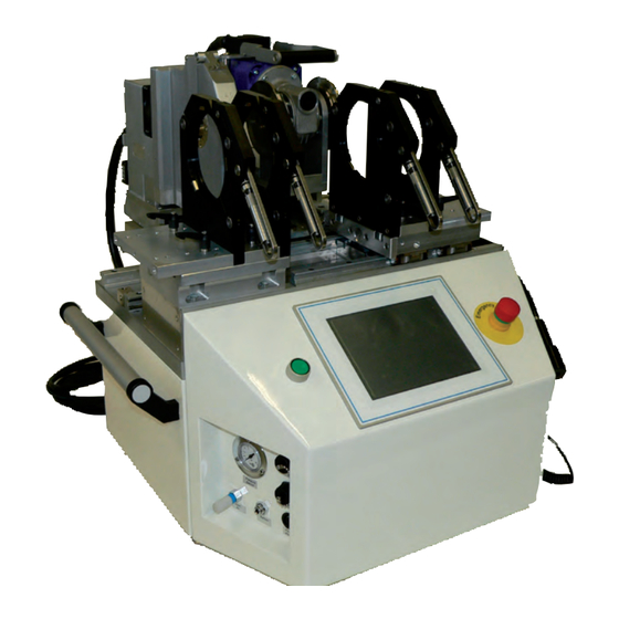
- Page 1 User’s Manual Inside and Outside Beadless Butt-welding Machine SP 110-B...
-
Page 2: Table Of Contents
Contents Introduction......................5 Safety Messages ....................5 The User's Manual ....................5 Explaining Icons ....................5 Safety Messages ....................6 Welder and Operator Obligations ................. 7 Warranty ....................... 7 Transport and Storage ..................7 Identifying the Machine ..................7 Product Description and Principles of Operation ..........8 Intended Use ...................... - Page 3 The machine has to be operated exclusively with a power supply line equipped with a protective grounding conductor, as a power supply without this safety element may cause severe machine Caution damage. If the machine is operated through a power supply without a grounding conductor, this will void any and all warranty under which the product may be.
-
Page 4: Introduction
Thank you. Safety Messages This User’s Manual contains important instructions for operating the beadless plastic welding machine agru SP 110-B safely. Every person who operates the machine will have to conform to the instructions of this manual. The machine has been developed and checked with respect to welding AGRU materials. -
Page 5: Safety Messages
Safety Messages Protect the power supply cord from cutting edges. Have an authorized service shop replace damaged cables or lines immediately. The machine has to be operated with a 230 V, 50/60 Hz power supply with safety fuse or breaker of 16 A. If power is connected through a power line manifold, the power supply has to feature an earth-leakage circuit breaker. -
Page 6: Welder And Operator Obligations
Ensure that transport lock is engaged during transport. Infrarot-Stumpfschweißmaschine The transport box should also be used to store the machine. The machine agru SP 110-B has to be stored in a dry location, be clean or has to be cleaned, and be 01211039 locked against unwanted operation. -
Page 7: Product Description And Principles Of Operation
Product Description and Principles of Operation Intended Use The agru SP 110-B Welding Machine is designed exclusively for welding plastic pipes and fittings using the inside and outside beadless butt- welding technique. Only the welding parameters shown on the touchscreen display (prepro- grammed by the manufacturer or defined by the user) can be selected for a welding operation. -
Page 8: Touchscreen / Control Panel
3.2.2 Touchscreen / Control Panel A G R U S P 1 1 0 - 0 4 . 0 5 . 2 0 1 0 0 9 : 1 5 + + + + + Status Bar C o o l i n g P h a s e Title Band Multifunctional Area (changes... -
Page 9: Specifications
All welding reports can the be printed or transferred to a computer with a suitable pipeline management software (such as DataWork agru). Using the menus displayed on the touchscreen, the machine can be customized to the application at hand (see section 4.3, Configuring the... -
Page 10: Operation
Operation Prior to the first use of the machine, the transport lock has to be removed. Damage due to non-compliance with this provision will no be ineligible for warranty. Important Check-out, Turning on, Selecting the Display Language Place the machine on a level surface and ensure it cannot slide. Suffi- cient distance has to be kept to other areas in the workshop, especially to those in which combustible materials are used, in order for the heating element temperature of up to 500°C (930°F) not to be hazardous. -
Page 11: Entering Traceability Data For The Joint
A G R U S P 1 1 0 - 0 6 . 0 5 . 2 0 1 0 0 9 : 3 1 + + + + + All inputs for which a bar code is available can be entered from the bar code using a scanning pen. -
Page 12: Configuring The Machine
Configuring the Machine A G R U S P 1 1 0 - 0 6 . 0 5 . 2 0 1 0 0 9 : 3 1 + + + + + In the first input screen of the welding pro- cess proper (Display 5), the key parameters U s e M a t e r i a l P a r a m s o f L a s t O p e r a t i o n ? of the last welding are shown (material,... -
Page 13: Changing Key Data Of The Welding
Designation Setting Description / Data to be entered (continued) Show Reports Menu In a sub-menu, it is possible to select a job number in order to display the welding reports of this commission. In report display mode, it is also possible to print a label tag for this welding once again (see section 5.2). - Page 14 Default Materials are those pipe materials A G R U S P 1 1 0 - 0 6 . 0 5 . 2 0 1 0 0 9 : 3 1 + + + + + that are defined by default when the machine is shipped.
-
Page 15: Definition Of Welding Parameters For Additional Materials
Definition of Welding Parameters for Additional Materials The configuration menu (see section 4.3) has an option “Additional Materials,” which allows defining the key data the machine should use when welding pipes of a material that is not currently available in the machine. -
Page 16: Welding Process
selected from all the key data that need to be defined. From that screen, an input screen is accessed in which the value can be changed; then confirm the change by touching the “Ok” button. The “Delete Parameters” button can be used to delete the “branch” of the data “tree,”... -
Page 17: Positioning The Inside Balloon
When the facing tool handle is located at A G R U S P 1 1 0 - 0 6 . 0 5 . 2 0 1 0 0 9 : 3 1 + + + + + Position 1, the machine asks the operator to close in the carriage (see Display 12). -
Page 18: Inserting The Heating Element
properly, touching the “Cancel” button causes the release of the air in the balloon and allows starting the positioning procedure over. 4.6.3 Inserting the Heating Element When the balloon is correctly placed, the machine tells the welder first to reposition the A G R U S P 1 1 0 - 0 6 . -
Page 19: Cooling Phase
4.6.6 Cooling Phase A G R U S P 1 1 0 - 0 6 . 0 5 . 2 0 1 0 0 9 : 3 1 + + + + + At the end of the joining stage, the ma- chine moves on automatically to the cool- ing phase (second-last LED in Display 16). -
Page 20: Printing And Transferring Welding Reports
USB stick and a USB B interface through which data can be transferred to a PC, e.g. with an installation of the DataWork agru software. The Print Menu and Printing/Transferring Reports... -
Page 21: Showing Reports In Memory, Reprinting Tags
to the connected device: to the a printer for A G R U S P 1 1 0 - 0 6 . 0 5 . 2 0 1 0 0 9 : 3 1 + + + + + print-out or to a PC for further processing and archiving. -
Page 22: Deleting Reports From Memory
To display the detailed view of the report, touch the “Detail” button or to reprint an extra tag of this welding operation for sticking it onto the pipe, the “Tag” button. Deleting Reports from Memory To delete the reports stored in memory, use the appropriate option in the configuration menu (see sub-section 4.3). -
Page 23: Service And Repair Contact
That the scales can now be cleaned is displayed on the screen. When the message to this effect appears, the welder can open the heating scale. When it is open, it is no longer heated. If the temperature decreases to the point where residues cannot be removed anymore, close the scale again and heating will resume automatically in an analogous manner as previously.
Need help?
Do you have a question about the SP 110-B and is the answer not in the manual?
Questions and answers