Table of Contents
Advertisement
Available languages
Available languages
Quick Links
Advertisement
Table of Contents

Related Manuals for Svan SCE1100ADB


Summary of Contents for Svan SCE1100ADB
- Page 1 2806-24 PIN: 2806DN0131 Manual de Instrucciones Calentador de agua a Gas instantádoméstico SCE1100ADB Modelo: SCE1300ADB Antes de utilizar su , lea atentamente este manual y consérvelo para futuras consultas.
-
Page 2: Table Of Contents
ÍNDICE DE CONTENIDOS 1. PRECAUCIONES 2. INTRODUCCIÓN DEL PRODUCTO 3. INSTALACIÓN DE LA UNIDAD 4. MÉTODOS DE USO 5. MANTENIMIENTO 6. SOLUCIÓN DE PROBLEMAS El calentador se corresponde con los requisitos estándar de la CE y de acuerdo con las siguientes directivas: (UE)2016/426;... -
Page 3: Precauciones
1. PRECAUCIONES 1.1 Precauciones especiales Cuando el calentador de agua funciona, la combustión de gas consumiría una gran cantidad de oxígeno y agotaría mucho monóxido de carbono. En vista del gran daño a la salud humana o incluso la muerte causada por la inhalación excesiva de monóxido de carbono, la compañía aconseja sinceramente a todos los usuarios que: ADVERTENCIA... -
Page 4: Otras Precauciones
Sin humo y fuego Cerrar la válvula de gas 1.3 Guardias contra fuego Está absolutamente prohibido salir de casa o irse a dormir si no se ha apagado un calentador de agua. No se colocan productos inflamables cerca de la campana extractora de un calentador de agua. La entrada de aire y la salida de escape no deben estar cubiertas por toallas, ropa, etc. -
Page 5: Introducción Del Producto
2. INTRODUCCIÓN DEL PRODUCTO 2.1 Parámetros de rendimiento técnico (Tabla 1) Modelo SCE1100ADB SCE1300ADB 2806DN0131 Aguja CE Consumo de energía V.ac Voltaje Nominal 230~ 230~ 230~ 230~ Frecuencia Categoría de gas 3B/P(30) 3B/P(30) 3+(28-30/37) 3+(28-30/37) 3P(37) 3P(37) G30/G31 G30/G31 Tipo de gas... - Page 6 Declare el perfil de carga Tipo de eficiencia energética del caldeo de agua Eficiencia energética del caldeo de agua 77.24 77.24 81.66 81.66 7.605 7.605 21.806 21.806 Consumo de gas diario (Corregido) Consumo eléctrico diario (Corregido) 0.12783 0.1168 0.1168 0.12783 Consumo de combustible anual AFC mg/kWh 54.5...
- Page 7 Diámetro Long. Alt. Anch. ADVERTENCIA Las especificaciones de la placa se deben tomar como estándar para categoría de gas especial. ¡El re-equipamiento o el cambio por otros tipos de gas no están permitidos! 2.2 Diagrama estructural interno escape Interruptor de presión de aire Instalación del ventilador...
-
Page 8: Características Funcionales
2. Características funcionales Diseño sellado Ajuste automático de la temperatura del agua: regulador proporcional avanzado, la temperatura del agua puede mantenerse constante a la temperatura preestablecida (35~65℃) . Pantalla digital y configuración de la temperatura del agua de salida, fácil y conveniente de usar. Indicador de fuente de alimentación, indicador de quemado, sistema de alarma diplex acústico-óptico para atraer la atención del usuario, más seguro de usar. -
Page 9: Instalación De La Unidad
2.4 Diagrama de cable interno Tierra Alimentación Motor DC A la pantalla Válvula proporcional Interruptor Interruptor sobrecalentamiento válvula salida NTC entrada NTC sensor de desbordamiento tierra detector de llama sensor de presión del viento Varillas de ignición 3. INSTALACIÓN DE LA UNIDAD 3.3 Modos de instalación La rejilla de entrada de aire de combustión debe ubicarse en un lugar bien ventilado. -
Page 10: Breve Introducción
ADVERTENCIA Esta unidad debe instalarse en interiores y no debe instalarse en exteriores. Nunca use esta unidad cuando no haya un suministro de gas obligatorio ni un tubo de escape instalado. 3.2 Breve introducción El calentador de agua debe ser instalado por técnicos con calificaciones profesionales para la instalación. Dado que la instalación incorrecta puede provocar fallas, los clientes no deben instalar el calentador por sí... -
Page 11: Instalación De La Unidad
Instalación de la unidad: Monte la unidad en posición vertical sin inclinación de acuerdo con la dimensión que se muestra en la siguiente ilustración. Más de 300mm Más de 150 mm Más de 150 mm Más de 600mm Tipo de instalación (C12) Instalación del tubo de suministro y escape obligatorio de la unidad: a. - Page 12 Como se muestra en la imagen siguiente, ajuste los tornillos expansores para fijarlos, cuelgue la unidad verticalmente y atorníllela con tuercas, inserte tapones de plástico debajo de este y atornille los autorroscantes. Teniendo en cuenta la inclinación de montaje de 3°, esta dimensión se determinará por la posición de montaje de la unidad en relación a la pared lateral.
- Page 13 Tipo de instalación (C32) Instalación del tubo de suministro y escape obligatorio de la unidad: a. Modo de instalación del escape superior. Tubo de suministro y escape Tornillo autorroscante Tornillo autorroscante ST4.2×6.5 Como se muestra en la imagen siguiente, ajuste los tornillos expansores para fijarlos, cuelgue la unidad verticalmente y atorníllela con tuercas, inserte tapones de plástico debajo de este y atornille los autorroscantes.
- Page 14 Tipo de instalación (B22) Instalación del tubo de suministro y escape obligatorio de la unidad: a. Modo de instalación del escape superior. Sello de empaque Tubo de suministro y escape Codo Inclinación hacia debajo de 3° Tornillo autorroscante Instrucciones de instalación del adaptador Salida del ventilador Adaptador Retire la tubería vieja y vea la salida del ventilador.
- Page 15 b. Modo de instalación del escape de la parte superior trasera. Sello de empaque Inclinación hacia debajo de 3° Como se muestra en la imagen siguiente, ajuste los tornillos expansores para fijarlos, cuelgue la unidad verticalmente y atorníllela con tuercas, inserte tapones de plástico debajo de este y atornille los autorroscantes.
- Page 16 Instalación de tubería de gas. a. Precaución La longitud de la manguera de goma no debe exceder los 2 metros. La manguera de goma debe estar conectada en la posición de la línea roja de la junta de entrada de gas y asegurada con una abrazadera. Conecte la unidad a la junta de gas con una rosca de tubo G1/2.
- Page 17 3.4 Precaución de instalación Como este aparato adopta entrada y salida de aire obligatorio, está permitido que se lo instale en el baño, sin embargo, la salida del sistema de escape se debe extender al exterior y la distancia entre el extremo del tubo de escape exterior y el adyacente u otros artículos debe ser mayor a 600mm.
-
Page 18: Métodos De Uso
Se debe instalar un receptáculo conectado a tierra de manera confiable, a la izquierda o a la derecha de la unidad. 4. MÉTODOS DE USO 4.1 Preparación antes de la ignición Inserte el enchufe de la fuente de alimentación y enciéndalo. Abra el interruptor principal de la válvula de gas. - Page 19 Finalice la preparación arriba mencionada y confirme antes de utilizar. Finalice la preparación arriba mencionada y confirme antes de utilizar. Pulse la tecla de ON/OFF (ENCENDIDO/APAGADO) en el panel de operación, el LED mostrará la temperatura de salida de agua predeterminada de 4℃, pulse la tecla para configurar la temperatura de salida de agua caliente.
- Page 20 ADVERTENCIA Para volver a usar agua caliente después de parar, no permita que el agua caliente lo salpique, ya que la temperatura del agua en la unidad puede ser muy alta. Úselo después de varios segundos de salida de agua caliente para evitar escaldaduras. 4.3 Deje de usarlo Cierre la válvula de salida de agua, la unidad se detendrá...
- Page 21 NOTA Si el flujo es inestable, confírmelo 30 minutos más tarde. En climas fríos, asegúrese de aumentar el flujo de agua. Método de drenaje anti-congelante: Cuando hay un controlador de línea, la tecla de ON/OFF (ENCENDIDO/APAGADO) del mismo debe estar en la posición APAGADO y la unidad debe funcionar de la siguiente manera: Cierre la válvula de gas.
-
Page 22: Mantenimiento
5. MANTENIMIENTO ADVERTENCIA Desenchufe el cable eléctrico antes de limpiar o del mantenimiento. Revise con frecuencia para ver si las tuberías de suministro de gas (manguera de goma) están en buenas condiciones sin envejecimiento, grietas. Preste atención al reemplazo periódico de las mangueras de goma. - Page 23 Visualización avanzada del código de error para un funcionamiento y mantenimiento más convenien tes. Códigos de error: Cód. Descripción Procedimiento Error Póngase en contacto con el servicio técnico. El sistema debe Fallo del motor reiniciarse manualmente para eliminar los códigos de error. Compruebe si el sensor de temperatura del agua de salida está...
- Page 24 Las cañerías de gas de agua continuamente varias están llenas de aire veces hasta que se logra el encendido Presión de Pídale al personal de mantenimiento que controle la válvula de regulación de la inapropiada presión de gas Póngase en contacto con el Congelamiento personal de mantenimiento Entrada con presión...
- Page 25 ADVERTENCIA No utilice calentadores con fallas. ELIMINACIÓN DE LOS EMBALAJES Y DEL PRODUCTO Deseche el material de embalaje del aparato correctamente. Todos los materiales de embalaje pueden ser reciclados. Las piezas de plástico están marcadas con las abreviaturas internacionales estándar: (por ejemplo, PS para poliestireno, material de relleno) Este aparato está...
- Page 26 2806-24 PIN: 2806DN0131 Instruction Manual Domestic Instantaneous Gas Water Heater SCE1100ADB Model: SCE1300ADB Thank you very much for purchasing our water heater. Before installing and operating your water heater, please read this manual carefully and keep it for future reference.
- Page 27 TABLE OF CONTENTS TITLE PAGE 1. CAUTIONS ............................2 2. PRODUCT INTRODUCTION ......................4 3. UNIT INSTALLATION .........................8 4. METHODS OF USING ........................17 5. MAINTENANCE ..........................21 6. TROUBLESHOOTING ........................21 The heater corresponds to requirements of CE standard, and accord with the following directives: (EU)2016/426 ;legal Facilities directives of the Member States for Natural Gas Installation.
-
Page 28: Cautions
1. CAUTIONS 1.1 Special Cautions When the water heater is working, gas combustion would consume a large amount of oxygen and exhaust much carbon monoxide. In view of the great harm to the human health or even death caused by excessive carbon monoxide inhalation, the company sincerely advises all users that: The water heaters must be correctly installed and used according to the requirements of this manual. -
Page 29: Other Cautions
No smoke and fire Close gas valve 1.3 Guards Against Fire It is absolutely forbidden to leave home or go to sleep under the circumstance that a water heater hasn’t gone out. No inflammable goods placed near the fume hood of a water heater. The air intake and the exhaust exit shall not be covered by towels, clothing, etc. -
Page 30: Product Introduction
2. PRODUCT INTRODUCTION 2.1 Technical Performance Parameters (Table 1) Model SCE1100ADB SCE1300ADB 2806DN0131 CE-Pin Power Consumption Rated Voltage V.ac 230~ 230~ 230~ 230~ Frequency Gas Category 3B/P(30) 3B/P(30) 3+(28-30/37) 3+(28-30/37) 3P(37) 3P(37) Gas Type G30/G31 G30/G31 Gas pressure 28-30 28-30... - Page 31 Declare load profile Water heating energy efficiency class η Water heating energy efficiency 77.24 77.24 81.66 81.66 Daily gas consumption (Corrected) kWh 7.605 7.605 21.806 21.806 Daily electrical consumption (Corrected) 0.12783 0.1168 0.1168 0.12783 Annual fuel consumption AFC mg/kWh 54.5 38.13 46.57 23.75...
- Page 32 WARNING The specifications given on the nameplate shall be taken as the standard for special category of gas. Re-equipment or changing into other gas types is not allowed! 2.2 Internal Structural Diagram Flue exhaust pressure switch Thermostat Gas proportional valve Heat exchanger Influent connecting pipe...
-
Page 33: Functional Features
2.3 Functional Features Sealed Design: the air inlet and exhaust are completely isolated from the air in the room, so the water heater can be installed in the bathroom. Automatic Adjustment Of Water Temperature: advanced proportional regulator, the water tempera-ture can be kept constant at preset temperature (35~65 ℃) . -
Page 34: Internal Wire Diagram
2.4 Internal wire Diagram ground power DC fan to display proportional valve over heating switch switch valve inlet NTC outlet NTC water flow sensor ground flame detect wind pressure sensor ignition poles 3. UNIT INSTALLATION 3.3 Installation Modes The combustion air intake grille must locate in a well-ventilated place. To prevent corrosion, it is necessary that the combustion air is free of aggressive substances. -
Page 35: Brief Introduction
WARNING This unit must be installed indoors and must not be installed outdoors. Never use this unit when no compulsory gas supply and exhaust pipe is installed. 3.2 Brief Introduction The water heater must be installed by technicians with professional qualifications for installation. Since the improper installation is liable to failures, the customers shall not install the heater by themselves. - Page 36 Installation of the unit: Mount the unit upright without inclination according to the dimension show in the following illustration. More than 300mm More than 150mm More than 150mm More than 600mm Type of installation (C12) Installation of compulsory gas supply and exhaust pipe of the unit: a.
- Page 37 As show in the figure below, tap in expansion screws for fixation, hang the unit vertically and screw it down with nuts, insert plastic plugs below it and screw down self-tapping screws. Considering the mounting inclination of 3°, this dimension will be determined on the unit’s mounting position relative to the sidewall.
- Page 38 Type of Installation (C32) Installation of compulsory gas supply and exhaust pipe of the unit: a. Installation mode of topside exhaust. Supply and exhaust pipe Self-tapping screw Self-tapping screw ST4.2×6.5 As show in the figure below, tap in expansion screws for fixation, hang the unit vertically and screw it down with nuts, insert plastic plugs below it and screw down self-tapping screws.
- Page 39 Type of Installation (B22) Installation of compulsory gas supply and exhaust pipe of the unit: a. Installation mode of topside exhaust. Packing seal Exhaust pipe Elbow Incline downward by 3° Self-tapping screw Adapter installation instruction: Fan outlet Adapter Remove the old pipe and see the outlet of the fan. Insert the adapter down the fan outlet into the upper part of the fan.
- Page 40 b. Installation mode of top rear exhaust. Packing seal Incline downward by 3° As show in the figure below, tap in expansion screws for fixation, hang the unit vertically and screw it down with nuts, insert plastic plugs below it and screw down self-tapping screws. 100 round hole Wall-through hole 1 mounting hole for...
- Page 41 Installation of gas pipe a. Caution Be sure to select a special gas rubber hose or a suitable rigid tube and a gas relief valve. Select the pipe size according to Table 1. The length of the rubber hose shall not exceed 2 meters. The rubber hose must be connected to the red line position of the gas inlet joint and secured with a clamp.
-
Page 42: Installation Caution
3.4 Installation Caution Since this machine adopts compulsory air inlet and exhaust, it is permissible to be installed in the bathroom, however, the exit of exhaust system must be extended outdoors, and the distance between the end of outdoor exhaust pipe and adjacent or other articles must be larger than 600mm. This machine is not allowed to be installed outdoors to prevent damage of the heater caused by freezing of water. -
Page 43: Methods Of Using
Receptacle shall be installed on the left or right side of the unit and must be grounded reliably . 4. METHODS OF USING 4.1 Preparation Before Ignition Insert the power supply plug and switch on the power. Open the main gas valve switch. Open the water inlet valve before ignition. -
Page 44: Ignition And Operation
Finish above mentioned preparation and confirmation before use. Finish above mentioned preparation and confirmation before use. Press ON/OFF key on the operation panel, the LED will display the default water outlet temperature of Press ON/OFF key on the operation panel, the LED will display the default water outlet temperature of 4 , press the 4 , press the key to set the hot water outlet temperature. - Page 45 WARNING To use hot water again after stop, do not let the hot water splash you, because the water temperature in the unit might be very high. Use it after several seconds of hot water outflow to avoid scald. 4.3 Stop To Use Close the water outlet valve, the unit will stop automatically.
- Page 46 NOTE Since the flow is unstable, please confirm the flow again 30 minutes later. In cold weathers ,be sure to increase the water flow. Ani-frozen drainage method: When there is a line controller, the ON/OFF key of the line controller shall be at the OFF position and the unit shall be operated as follows: Close the gas valve.
-
Page 47: Maintenance
5. MAINTENANCE WARNING Take the electrical plug out before clean or maintenance. Check up frequently to see whether the gas supply pipelines (rubber hose) are in good conditions without aging, cracks. Pay attention to periodic replacement of rubber hoses. In order to prevent gas leakage, check the joints of pipelines frequently by using suds to see if there are bubbles given off. - Page 48 Advanced error code display for more convenient operation and maintenance. Error codes: Error Description Treatment codes Contact Midea for after-sales treatment. The system need to reset by Fan failure manual to eliminate error codes. Check whether the outlet water temperature sensor is damaged. If so, Outlet temperature sensor error replace the part and system can recover by itself.
- Page 49 If other failures are encountered, stop use of the water heater immediately, and notify the professional maintenance department for repair. The users shall not remove or repair the water heaters without prior permission, otherwise an accident might occur.
- Page 50 WARNING No use of water heaters with any failures. DISPOSAL OF PACKAGING AND Dispose of packaging in an environmentally-friendly manner. This appliance is labelled in accordance with European Directive 2012/19/EU concerning used electrical and electronic appliances (waste electrical and electronic equipment - WEEE). The guideline determines the frame work for the return and recycling of used appliances as applicable throughout to the EU.
- Page 51 2806-24 PIN: 2806DN0131 Aquecedor de água a gás instantâneo doméstico SCE1100ADB Modelo: SCE1300ADB Antes de utilizar su , lea atentamente este manual y consérvelo para futuras consultas.
- Page 55 2. INTRODUCCIÓN DEL PRODUCTO 确认翻译 2.1 Parámetros de rendimiento técnico (Tabla 1) Modelo SCE1100ADB SCE1300ADB 2806DN0131 Aguja CE Consumo de energía V.ac Voltaje Nominal 230~ 230~ 230~ 230~ Frecuencia Categoría de gas 3B/P(30) 3B/P(30) 3+(28-30/37) 3+(28-30/37) 3P(37) 3P(37) Tipo de gas...
- Page 56 确认翻译 Declare el perfil de carga Tipo de eficiencia energética del caldeo de agua Eficiencia energética del caldeo de agua 77.24 77.24 81.66 81.66 7.605 7.605 21.806 21.806 Consumo de gas diario (Corregido) 0.12783 Consumo eléctrico diario (Corregido) 0.1168 0.1168 0.12783 Consumo de combustible anual AFC mg/kWh...
- Page 57 ADVERTÊNCIA Exaustão da chaminé Pressão do ar Ventilador Termostato Válvula proporcional de gás Trocador de calor Tubulação de conexão influente Conjunto da agulha de ignição Sensor de temperatura de entrada de água Queimador Válvula de liberação de pressão/válvula de Saída de água Painel de controle extração de água Plugue de alimentação...
- Page 58 ℃...
- Page 59 2.5 DDiagrama de cabos internos 3.3 Modos de instalação...
- Page 60 ( ) Nombre e ilustraciones Cantidad Nombre e ilustraciones Cantidad Tornillo de Calentador de expansión M6 agua Tornillo de rosca Manual de Instrucciones Conector de tubería de gas Tapón de plástico Tornillo de sellado de anillo 无翻译...
- Page 61 Sello de empaque Tubo de suministro y escape Codo Inclinación hacia debajo de 3° 无翻译 Tornillo autorroscante...
- Page 65 NOTA...
- Page 66 NOTA...
- Page 68 4.1 PPreparação antes da ignição ② ③ NOTA...
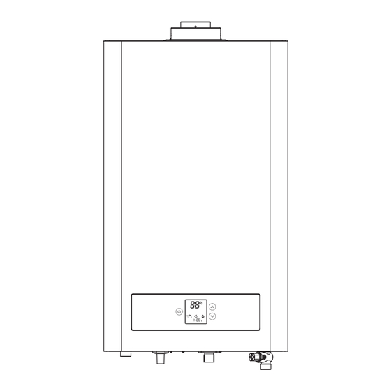
- Page 69 ℃ Indicación de Tecla de aumento de temperatura del temperatura agua de salida Tecla de disminución de temperatura Tecla ENCEND - DO/APAGADO Indicación de quemado Indicación de 无翻译 flujo de agua Fijar temperatura Indicación de funciona miento de turbina NOTA ℃...
- Page 71 NOTA NOTA...
- Page 73 Cód. Descripción Procedimiento Error Póngase en contacto con el servicio técnico. El sistema debe Fallo del motor reiniciarse manualmente para eliminar los códigos de error. Compruebe si el sensor de temperatura del agua de salida está dañado. Si Error del sensor de temperatura de salida es así, reemplace la pieza y el sistema puede recuperarse por sí...
- Page 75 DESCARTE DA EMBALAGEM El producto está sujeto a cambios sin aviso. Por favor, guarde este manual adecuadamente. 无翻译...
Need help?
Do you have a question about the SCE1100ADB and is the answer not in the manual?
Questions and answers