Advertisement
Quick Links
Advertisement

Subscribe to Our Youtube Channel
Related Manuals for crosscontrol CCpilot V705

Summary of Contents for crosscontrol CCpilot V705
- Page 1 Revision: PA1 2024-10-25 CCpilot V705 Technical Manual www.crosscontrol.com...
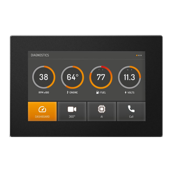
- Page 2 This technical manual provides important information regarding the CCpilot V705 product’s hardware and its basic usage. The CCpilot V705 is a 7” display computer products featuring an i.MX 8DualXPlus application processor. For software and operating system specifics, please see additional documentation.
- Page 3 CCpilot V705 Revision: PA1 Technical Manual 2024-10-25 Contents 1. Introduction ..........................2 Revision history ..........................2 2. Product models ........................... 4 2.2. Document conventions ...................... 4 2.3. Identification......................... 5 2.4. Environmental resistance ....................5 3. Product overview ........................6 3.1. Front side view ........................6 3.2.
- Page 4 Technical support ........................... 35 Trademarks and terms of use ....................... 36 2. Product models This documentation is applicable for all CCpilot V705 models. 2.1.1. Customized models The platform enables additional customization of hardware and software. Described herein are the features included in product models described above. Additional features in customized models will be documented separately.
- Page 5 Technical support and Service/Repair needs. Figure 1: Identification labels 2.4. Environmental resistance The CCpilot V705 product has been designed to manage tough environmental demands. The focus, from design through components selection, has been to provide a reliable and robust device.
- Page 6 Technical Manual 2024-10-25 3. Product overview This chapter contains illustrations of the CCpilot V705 showing the location of external connectors, indicators etc. Connectors are described in more detail in chapter 7. Additional mechanical information can be found in chapter 8.4.
- Page 7 ® Deutsch DTM connector 2 GORE-TEX membrane, under mount for added protection 3 x M5 inserts Deutsch DTM connector 1 Figure 3 CCpilot V705 rear view CCpilot V705 contains mounting holes in accordance 1.5” RAM® ball mount (RAM-202U) www.crosscontrol.com...
- Page 8 6 mm to avoid pulling out the threaded inserts from the unit. 4.1.1. CCpilot V705 RAM mount CCpilot V705 can be mounted using a RAM mount, i.e. RAM-202U, a round base 1.5” ball mount and accessories of choice which allows adjustment of the display’s position and angle. Screw length should be 12mm.
- Page 9 Alternatively, the device can be mounted in a panel cut-out using a panel mounting bracket with spacer and screw. Figure 5: CCpilot V705 mounting bracket. The mounting bracket is designed for a panel thickness of 1.5 - 3.0 mm. Panel cut out dimensions are shown in the figure below.
- Page 10 2024-10-25 Figure 6: Panel cut-out CCpilot V705 Ensure that CCpilot V705 is mounted to a smooth, flat surface. Fastening the unit to an uneven surface may stress the enclosure, damage the outer flange, or possibly even flex the circuit board inside, leading to a premature failure.
- Page 11 4.2.4. Application example Below is an application example schematic of the CCpilot V705 power supply connection. If the system has a main switch for completely disconnecting the battery (S1 in schematic below), the device’s power supply and key switch signal shall be connected after the main switch.
- Page 12 (S2) is closed and shut down when the switch is opened. Note that the on/off behaviour of the CCpilot V705 described here is the default configuration. Its response to the on/off signal may be altered using the CCAux API, see chapter 5.1 for more details.
- Page 13 When using shielded cables for Ethernet, the shield is preferably connected/grounded at the other end of the cable (and remain unconnected close to the CCpilot V705 device). Below are recommendations for inserting cable shields and coaxial cables into Deutsch DTM plugs to achieve robust connections and retaining IP classification of the device.
- Page 14 Always consider personal safety when installing and operating the product. For example, • in vehicle installations, CrossControl does not recommend that the product is being actively operated by the driver when there is a risk of injury to people or property damage.
- Page 15 LED will stop flashing and be turned on. 5.2. Turning OFF and suspending There are several ways to turn off the CCpilot V705 device and alternatives to enter suspend mode instead of completely shutting down the device.
- Page 16 CCAux API. See the software guide for details. 5.2.3. Forced Shutdown If the CCpilot V705 is not responding, a forced shutdown can be performed by removing power. A forced shutdown immediately shuts down the device, regardless of its operational state. Any information which was not saved will be lost when performing a forced shutdown.
- Page 17 2024-10-25 5.3. Light sensor and screen brightness The CCpilot V705 contains a light sensor that can be used to automatically adjust the display brightness, depending on the ambient light conditions. As depicted in Figure 2, the light sensor is located in the upper right corner of the front surface. When automated dimming is enabled, the level of sensitivity can be adjusted.
- Page 18 The error code in persistent storage can be read and cleared from a user application. Refer to Table 2: CCpilot V705 system related error codes for a complete listing of the error codes. The number of blinks is important information if the unit is sent in for service/repair.
- Page 19 CCpilot V705 Revision: PA1 Technical Manual 2024-10-25 Table 3: CCpilot V705 display related error codes Error code Error code name Likely problem cause ERR_NO_ERROR Default entry, log entry never written. Invalid log entry, i.e failed to read the ERR_INVALID_LOG_ENTRY log entry from EEPROM.
- Page 20 Refer to the CCpilot V705 Software guide for details about accessing the light sensor data from within user applications. 6.3. RGB status LED The CCpilot V705 contains a status LED in the front used for notification while starting up, shutting down or in other operational states. 6.4. Buzzer The CCpilot V705 has a built-in buzzer that can be used for audible notifications.
- Page 21 IT security threat. 6.7. USB The CCpilot V705 has one USB port. This port supports an USB OTG interface, (can act as both host and device). Using the port in USB device mode is only for OS updates through a connected PC with appropriate tool installed.
- Page 22 2024-10-25 electromagnetic compliance. Depending on installation the shield could be connected to USB ground or left unconnected on the Deutsch DTM-12 connector, i.e. CCpilot V705, side of the cable. 6.8. Bluetooth and Wi-Fi The CCpilot V705 offer an optional built in Bluetooth and Wi-Fi module to facilitate wireless communication to and from the device.
- Page 23 CCpilot V705 Revision: PA1 Technical Manual 2024-10-25 In frequency mode a combination of measuring the number of pulses during a certain time (~30Hz update rate) and measuring the exact time for those pulses using a timer is used to get a good resolution in a wide range of frequencies.
- Page 24 CCpilot V705 Revision: PA1 Technical Manual 2024-10-25 Each output provides diagnostics/fault-detection for both ON- and OFF-state according to below: Error code (hint) Output off Output on 0 = OK (no error present) 1 = Short to Ground (STG) 2 = Short to Battery (STB)
- Page 25 CCpilot V705 Revision: PA1 Technical Manual 2024-10-25 External voltage applied to output pins will supply the unit backwards, via diode in high side switch, if the voltage at pin is higher than supply voltage. This might start the unit unintentionally if not powered on.
- Page 26 CCpilot V705 Revision: PA1 Technical Manual 2024-10-25 7. Connectors All connectors are accessible from the rear of the unit. The connectors, twelve pin molded-in Deutsch DTM series, are marked with a 1(J1) and a 2(J2). Use caution and avoid plugging/unplugging of connectors when the computer is powered up.
- Page 27 CCpilot V705 Revision: PA1 Technical Manual 2024-10-25 Figure 13: CCpilot 705 Connector numbering and placement. 7.2. Deutsch DTM connectors, general Use caution and avoid plugging/unplugging Deutsch DTM connectors while the device is powered up. If a connector pin becomes bent the interface may not function correctly and the device should be returned to the manufacturer for repair.
- Page 28 CCpilot V705 Revision: PA1 Technical Manual 2024-10-25 8. Specifications 8.1. Technical data Temperature specification Operating -30 to +70 °C Storage -40 to +80 °C Kernel Main Processor ® NXP™ i.MX8 DualXPlus: ARM 64-bit, 1200MHz, Cortex -A35 Co-processor ® STMicroelectronics STM32G070RBT6, Cortex...
- Page 29 CCpilot V705 Revision: PA1 Technical Manual 2024-10-25 USB 2.0 interfaces Type 1x USB 2.0 compatible host ports Speed Full-speed (12 Mbps) and Hi-speed USB (480 Mbps) is supported. 5.0 V, 0.5 A per port, internally over-current (typically 0.7 A) and VBUS supply short-circuit to ground protected.
- Page 30 CCpilot V705 Revision: PA1 Technical Manual 2024-10-25 Range 0 – 38.2 V Accuracy ± (0.5% + 100 mV) Resolution 1 mV Input Impedance 82kΩ at 0-3V, 36kΩ at >3V (typical) Resistance measurement Range Ω kΩ – 2.4 Accuracy (typ) ±0.25Ω...
- Page 31 The buzzer is located on the back (connector side) of the device and the typical SPL varies dependent on the acoustic properties of the installation environment and mounting hardware. Software Operating system CC Linux CCAux API, CCSettingsConsole. Refer to the CCpilot V705 Software Additional software Guide and Programmer’s guide for details. Display CCpilot V705 Size Diagonal size7”...
- Page 32 Enclosure Ingress Protection IEC 60529:2014 IP65, IP66 and IP67 Any changes or modifications to the device not expressly approved by CrossControl could void the environmental classification, warranty, and user's authority to operate the equipment. 8.3. EMC specification The CCpilot V705 device has been tested for Electromagnetic Compatibility according to the following standards EN ISO 14982 and ISO 13766-1.
- Page 33 8.4. Weight and dimensions Attribute Description Comments 200 x 134 x 35,5 (47 mm (W x H x D) CCpilot V705 Dimensions CCpilot V705 Weight 0.650 kg RAM-202U Mounting holes V710 Spacing Dia 46 mm...
- Page 34 CCpilot V705 Revision: PA1 Technical Manual 2024-10-25 Figure 14: CCpilot V705 dimensions www.crosscontrol.com...
- Page 35 Technical Manual 2024-10-25 Technical support Additional sources of information are available on the CrossControl support site: http://www.crosscontrol.com/support Contact your reseller or supplier for help with possible problems with your device. In order to get the best help, you should have your device in front of you and be prepared with the following information before you contact support.
- Page 36 CrossControl. CrossControl respects the intellectual property of others, and we ask our users to do the same. Where software based on CrossControl software or products is distributed, the software may only be distributed in accordance with the terms and conditions provided by the reproduced licensors.
Need help?
Do you have a question about the CCpilot V705 and is the answer not in the manual?
Questions and answers