
Related Manuals for crosscontrol CCpilot V510

Summary of Contents for crosscontrol CCpilot V510
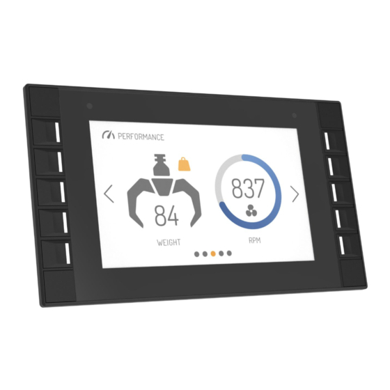
- Page 1 Revision: PA3 2024-04-22 CCpilot V510 and V710 Technical Manual www.crosscontrol.com...
-
Page 2: Introduction
This technical manual provides important information regarding the CCpilot V510 and V710 product’s hardware and its basic usage, hereinafter referred to as CCpilot V510/V710. The CCpilot V510/V710 are 5” and 7” display computer products featuring an i.MX 8DualXPlus application processor. -
Page 3: Table Of Contents
CCpilot V510/V710 Revision: PA3 Technical Manual 2024-04-22 Contents 1. Introduction ..........................2 Revision history ..........................2 2. Product models ........................... 4 2.2. Document conventions ...................... 4 2.3. Identification......................... 5 2.4. Environmental resistance ....................5 3. Product overview ........................6 3.1. Front side view ........................6 3.2. -
Page 4: Product Models
8.4. Weight and dimensions ..................... 36 Technical support ........................... 39 Trademarks and terms of use ....................... 40 2. Product models This documentation is applicable for all CCpilot V510/V710 models. These models are: CCpilot V510 • CCpilot V510 touch screen Wi-Fi and Bluetooth •... -
Page 5: Identification
Technical support and Service/Repair needs. Figure 1: Identification labels 2.4. Environmental resistance The CCpilot V510/V710 products has been designed to manage tough environmental demands. The focus, from design through components selection, has been to provide a reliable and robust device. -
Page 6: Product Overview
RGB status LED shows operation modes or fault indications. All display variants are optical bonded and have an anti-glare treatment. The number of soft buttons depends on product model. CCpilot V510 has 8 in 2*4 configuration and CCpilot V710 has 10 in a 2*5 configuration as shown below. -
Page 7: Rear Side View
RAM mount or custom bracket for panel mounting and a GORE-TEX membrane for ventilation. ® GORE-TEX membrane, under mount for added protection 2 x M5 inserts Deutsch DTM Deutsch DTM connector 1 connector 2 Figure 4 CCpilot V510 rear side view www.crosscontrol.com... - Page 8 CCpilot V510/V710 Revision: PA3 Technical Manual 2024-04-22 CCpilot V510 contains mounting holes in accordance with AMPS hole pattern (RAM 2.43” x 1.31” Diamond Base) and CCpilot V710 in accordance with 1.5” RAM® ball mount (RAM-202U) 3 x M5 inserts GORE-TEX membrane,...
-
Page 9: Mounting And Handling
6 mm to avoid pulling out the threaded inserts from the unit. 4.1.1. CCpilot V510 RAM mount CCpilot V510 can be mounted using a RAM mount, i.e. RAM-B-238U, diamond plate 2.43" x 1.31" ball mount and accessories of choice which allows adjustment of the display’s position and angle. - Page 10 Figure 7: CCpilot V710 RAM-202U round base 4.1.3. CCpilot V510/710 panel mount Alternatively, the device can be mounted in a panel cut-out using a panel mounting bracket (article number C000156-65 for CCpilot V510 and C000157-65 for CCpilot V710) with spacer and screw. www.crosscontrol.com...
- Page 11 CCpilot V510/V710 Revision: PA3 Technical Manual 2024-04-22 Figure 8: CCpilot V510 mounting bracket. Figure 9: CCpilot V710 mounting bracket. www.crosscontrol.com...
- Page 12 Figure 10: Panel cut-out CCpilot V510 Figure 11: Panel cut-out CCpilot V710 Ensure that CCpilot V510/V710 is mounted to a smooth, flat surface. Fastening the unit to an uneven surface may stress the enclosure, damage the outer flange, or possibly even flex the circuit board inside, leading to a premature failure.
-
Page 13: Connecting To Power Supply
2024-04-22 4.2. Connecting to power supply This chapter describes how the CCpilot V510/V710 is preferably connected to the power supply of the equipment it is installed in. The principle is the same for vehicular and stationary installations. Carefully read through the following sub-chapters. They are critical for designing and adapting the electrical system of the equipment in which the CCpilot V510/V710 is installed. -
Page 14: Cable Installation
(S2) is closed and shut down when the switch is opened. Note that the on/off behaviour of the CCpilot V510/V710 described here is the default configuration. Its response to the on/off signal may be altered using the CCAux API, see chapter 5.1 for more details. -
Page 15: Special Considerations
When using shielded cables for Ethernet, the shield is preferably connected/grounded at the other end of the cable (and remain unconnected close to the CCpilot V510/V710 device). Below are recommendations for inserting cable shields and coaxial cables into Deutsch DTM plugs to achieve robust connections and retaining IP classification of the device. -
Page 16: Handling And Maintenance
Always consider personal safety when installing and operating the product. For example, • in vehicle installations, CrossControl does not recommend that the product is being actively operated by the driver when there is a risk of injury to people or property damage. -
Page 17: Basic Operation
LED will stop flashing and be turned on. 5.2. Turning OFF and suspending There are several ways to turn off the CCpilot V510/V710 device and alternatives to enter suspend mode instead of completely shutting down the device. - Page 18 CCpilot V510/V710 Revision: PA3 Technical Manual 2024-04-22 5.2.1. Shutting Down There are three ways to shut down the device, provided that it is in normal operational state when the action occurs: 1. By disconnecting the external on/off control for more than a specified time, i.e. using the turn-key functionality.
-
Page 19: Light Sensor And Screen Brightness
CCAux API. See the software guide for details. 5.2.3. Forced Shutdown If the CCpilot V510/710 is not responding, a forced shutdown can be performed by pressing and holding a pushbutton (that is configured as action trigger) until the device is switched off. -
Page 20: Using The Touch Screen
5.5. Status notification The CCpilot V510/V710 contains a status LED, in the front, used for notification while starting up, shutting down or in other operational states. The buzzer may also be used for user notifications. -
Page 21: Display Related Error Codes
The error code in persistent storage can be read and cleared from a user application. Refer to Table 2: CCpilot V510/V710 system related error codes for a complete listing of the error codes. - Page 22 CCpilot V510/V710 Revision: PA3 Technical Manual 2024-04-22 ERR_RCC Failed to configure clocks. Failed to access touch controller over ERR_TOUCH_I2C I2C. ERR_TOUCH_NUM_CONTACTS Max number of contacts exceeded. ERR_HID_START_TRANS_FAILED Failed to start a touch data transfer. ERR_HID_RX_BUFF_OVERRUN I2C HID receive buffer overrun.
-
Page 23: Interface Overview
Refer to the CCpilot V510/V710 Software guide for details about accessing the light sensor data from within user applications. 6.4. RGB status LED The CCpilot V510/V710 contains a status LED in the front used for notification while starting up, shutting down or in other operational states. 6.5. Buzzer The CCpilot V510/V710 has a built-in buzzer that can be used for audible notifications. -
Page 24: Ethernet
IT security threat. 6.8. USB The CCpilot V510/V710 has one USB port. This port supports an USB OTG interface, (can act as both host and device). Using the port in USB device mode is only for OS updates through a connected PC with appropriate tool installed. -
Page 25: Bluetooth And Wi-Fi
Shielded cables shall be used to ensure reliable communication and electromagnetic compliance. Depending on installation the shield could be connected to USB ground or left unconnected on the Deutsch DTM-12 connector, i.e. CCpilot V510/710, side of the cable. - Page 26 CCpilot V510/V710 Revision: PA3 Technical Manual 2024-04-22 6.10.1. Digital input and frequency measurement Digital and frequency inputs modes can be used for connecting simple logical signals (for example switch to battery/ground or various logic output sensors) or frequency-output sensors commonly used in industrial applications.
-
Page 27: Configurable Outputs
CCpilot V510/V710 Revision: PA3 Technical Manual 2024-04-22 6.11. Configurable outputs There are two configurable outputs available through Deutsch DTM-connector 1. Two self- protected high-side PWM outputs for switching various external loads such as buzzers, relays, solenoids, lamps or other resistive or inductive loads. PWM frequencies between 1-5000Hz are supported and duty cycle can be controlled with 12-bit resolution (0-4095). - Page 28 CCpilot V510/V710 Revision: PA3 Technical Manual 2024-04-22 Generic error is reported when the cause of error cannot be determined or when there is no specific error code available. To clear an error code, the user must explicitly set a new duty cycle (To just clear the error code without activating output duty cycle 0 can be set).
-
Page 29: Connectors
CCpilot V510/V710 Revision: PA3 Technical Manual 2024-04-22 7. Connectors All connectors are accessible from the rear of the unit. The connectors, twelve pin molded-in Deutsch DTM series, are marked with a 1(J1) and a 2(J2). Use caution and avoid plugging/unplugging of connectors when the computer is powered up. -
Page 30: Deutsch Dtm Connectors, General
Revision: PA3 Technical Manual 2024-04-22 Figure 18: Connector numbering and placement CCpilot V510/710. 7.2. Deutsch DTM connectors, general Use caution and avoid plugging/unplugging Deutsch DTM connectors while the device is powered up. If a connector pin becomes bent the interface may not function correctly and the device should be returned to the manufacturer for repair. -
Page 31: Specifications
CCpilot V510/V710 Revision: PA3 Technical Manual 2024-04-22 8. Specifications 8.1. Technical data Temperature specification Operating -30 to +70 °C Storage -40 to +80 °C Kernel Main Processor ® NXP™ i.MX8 DualXPlus: ARM 64-bit, 1200MHz, Cortex -A35 Co-processor ® STMicroelectronics STM32G070RBT6, Cortex... - Page 32 CCpilot V510/V710 Revision: PA3 Technical Manual 2024-04-22 CAN interfaces Type Non-isolated, ISO 11898-1, CAN 2.0B CAN transceiver NXP TJA1051T/3 Configurable 20 kbit/s – 1 Mbit/s.* CAN FD mode up to 5 Mbit/s. * Internal CAN bus filters have a capacitance of 100pF (typ) as stated in the J1939 specification. This Baud Rate puts restrictions on the CAN bus topology considering bus length, number of CAN nodes etc.
- Page 33 CCpilot V510/V710 Revision: PA3 Technical Manual 2024-04-22 Resolution 0.1 Hz Accuracy frequency 0.1% 35Hz to 1000Hz 0.2% 1000Hz to 2000Hz 0.4% 2000Hz to 5000Hz Accuracy duty cycle 35Hz to 1000Hz 1000Hz to 5000Hz Voltage measurement 5V Range 0 – 5.2 V Accuracy ±...
- Page 34 The buzzer is located on the back (connector side) of the device and the typical SPL varies dependent on the acoustic properties of the installation environment and mounting hardware. Software Operating system CC Linux CCAux API, CCSettingsConsole. Refer to the CCpilot V510/V710 Additional software Software Guide and Programmer’s guide for details. Display CCpilot V510 Size Diagonal size 5”...
-
Page 35: Environmental Specifications
CCpilot V510/V710 Revision: PA3 Technical Manual 2024-04-22 Type Brightness 900 cd/m (typ) LED Life time 50 000 h (typ) before brightness is reduced with 50 % (when operated with full brightness at 25 °C) (Note that sustained higher operating temperatures affects LED lifetime.) -
Page 36: Emc Specification
Revision: PA3 Technical Manual 2024-04-22 Any changes or modifications to the device not expressly approved by CrossControl could void the environmental classification, warranty, and user's authority to operate the equipment. 8.3. EMC specification The CCpilot V510/V710 device has been tested for Electromagnetic Compatibility according to the following standards EN ISO 14982 and ISO 13766-1. - Page 37 Mounting holes V510 Spacing 48.6mm Thread dimension Thread depth 8.0 mm RAM-202U Mounting holes V710 Spacing Dia 46 mm Thread dimension Thread depth 8.0 mm PBT + PC plastic, impact Enclosure material modified and flame retarded Figure 19: CCpilot V510 dimensions. www.crosscontrol.com...
- Page 38 CCpilot V510/V710 Revision: PA3 Technical Manual 2024-04-22 Figure 20: CCpilot V710 dimensions www.crosscontrol.com...
- Page 39 Technical Manual 2024-04-22 Technical support Additional sources of information are available on the CrossControl support site: http://www.crosscontrol.com/support Contact your reseller or supplier for help with possible problems with your device. In order to get the best help, you should have your device in front of you and be prepared with the following information before you contact support.
- Page 40 CrossControl. CrossControl respects the intellectual property of others, and we ask our users to do the same. Where software based on CrossControl software or products is distributed, the software may only be distributed in accordance with the terms and conditions provided by the reproduced licensors.
Need help?
Do you have a question about the CCpilot V510 and is the answer not in the manual?
Questions and answers