
Related Manuals for InCharg MOD-1721


Summary of Contents for InCharg MOD-1721
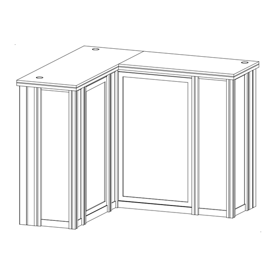
- Page 1 © 2024 Order #XXXXX MOD-1721 Backlit Counter BACK VIEW FRONT VIEW SETUP INSTRUCTIONS If you would like to tell us about your experience with your setup instructions please email us at info@classicexhibits.com...
-
Page 2: General Setup Instructions
© 2024 Order #XXXXX General Information WARNING General Setup Instructions - Read entire setup instruction manual prior to unpacking parts and pieces. - The setup instructions are created specifically DO NOT USE POWER TOOLS for this configuration. - Setup instructions are laid out sequentially in steps, including exploded views with detailed LADDERS OR LIFTS explanation for assembly. - Page 3 © 2024 Order #XXXXX CEI110 Frame Assembly Slide both connectors across seam of extrusions. Disassembly Tighten all knobs. Straight Connection 1) Loosen all knobs. Straight Connector When assembling frame, first attach all straight 2) Slide connectors off of one extrusion. connectors, then attach corner connectors.
- Page 4 © 2024 Order #XXXXX SEG Installation The Perfect Fit SEG Graphic Installation in 3 Steps STEP 1: Attach Corners STEP 2: Attach Middle STEP 3: Attach Sides Always insert graphic into each alternate corner, then into the sides of the frame. Otherwise the graphic will not fit into the frame correctly.
- Page 5 © 2024 Order #XXXXX Case Packing Top View of Each Level Shelf Counter Door Shelf Infills Level 1 Level 2 Level 3 Level 4 Level 5 Level 6 (Bottom level) Case 1 of 2...
- Page 6 © 2024 Order #XXXXX Case Packing Top View of Each Level 24 20 Graphics Counter Top Door 14 15 Setup Hardware Shelf Supports Bracket w/21A Bracket w/21 Infills Level 1 Level 2 Level 3 Level 4 Level 5 (Bottom level) Case 2 of 2...
-
Page 7: Counter Assembly
© 2024 Order #XXXXX Counter Assembly Item Qty. Description Steps: 39.5” S44 Vertical Extrusion 1) Assemble lower horizontals [7,8,9,10] between 39.5” S44 Vertical Extrusion verticals [1,2,3,4,5]. 39.5” S44 Vertical Extrusion 2) Slide Infills between verticals as shown. 39.5” S44 Vertical Extrusion 3) Attach upper horizontals [7A,8A,9A,10A], securing infills. - Page 8 © 2024 Order #XXXXX Counter Attachments Item Qty. Description 11,11A 35.853”h Z33 Vertical Extrusion Frame to Assembly Attachment 38.752” TSP2 Vertical Extrusion Z31 & Bracket Connection 21,21A 3.193” Z31 Horizontal Extrusion 39.5” CEI110 Vertical Extrusion CEI110 23,23A 45.75” CEI110 Horizontal Extrusion CEI110 39.5”...
-
Page 9: Completed Assembly
© 2024 Order #XXXXX Counter Attachments (cont’d) Steps: 1) Connect lighting power cords and attach transformers. See Light to Light Connection Light to Transformer Connection details. 2) Place shelves onto pins. See Shelf Pin detail. 3) Install SEG graphics to front of assembled frames. Refer to the SEG Installation general information page..
Need help?
Do you have a question about the MOD-1721 and is the answer not in the manual?
Questions and answers