Table of Contents
Advertisement
Quick Links
Operating
instructions
Base module
Version: 04.2021.0
ID: 900.000.0623
Product family CosiTherm®
Copyright 2021 AFRISO-EURO-INDEX GmbH. All rights reserved.
Type: BM
Lindenstraße 20
74363 Güglingen
Telephone+49 7135 102-0
Service+49 7135 102-211
Telefax +49 7135 102-147
info@afriso.com
www.afriso.com
Advertisement
Table of Contents

Related Manuals for Afriso EURO-INDEX CosiTherm Series


Summary of Contents for Afriso EURO-INDEX CosiTherm Series
- Page 1 Operating instructions Base module Product family CosiTherm® Type: BM Copyright 2021 AFRISO-EURO-INDEX GmbH. All rights reserved. Lindenstraße 20 74363 Güglingen Telephone+49 7135 102-0 Service+49 7135 102-211 Telefax +49 7135 102-147 info@afriso.com Version: 04.2021.0 www.afriso.com ID: 900.000.0623...
- Page 2 About these operating instructions About these operating instructions These operating instructions describe the base module "BM" (also referred to as "product" in these operating instructions). These operating instructions are part of the product. • You may only use the product if you have fully read and understood these operating instructions.
- Page 3 Information on safety Information on safety Safety messages and hazard categories These operating instructions contain safety messages to alert you to poten- tial hazards and risks. In addition to the instructions provided in these oper- ating instructions, you must comply with all directives, standards and safety regulations applicable at the installation site of the product.
-
Page 4: Information On Safety
Information on safety Intended use The base module is a part of CosiTherm®. This product may only be used to control the room temperature (heat/cool) of individual rooms with underfloor heating system. Any use other than the application explicitly permitted in these operating instructions is not permitted and causes hazards. -
Page 5: Transport And Storage
Transport and storage Qualification of personnel Only appropriately trained persons who are familiar with and understand the contents of these operating instructions and all other pertinent product docu- mentation are authorized to work on and with this product. These persons must have sufficient technical training, knowledge and expe- rience and be able to foresee and detect potential hazards that may be caused by using the product All persons working on and with the product must be fully familiar with all... - Page 6 Product description Product description Overview of the individual CosiTherm® components Component Versions Explanation Base module Timer module Wireless module With internal antenna for timer module With external antenna Room tempera- Wire ture sensor Wireless, temperature Wireless, temperature and humidity Controller module D2 Wired with 2 control circuits Wired with 6 control circuits Wireless with 2 control circuits...
-
Page 7: Product Description
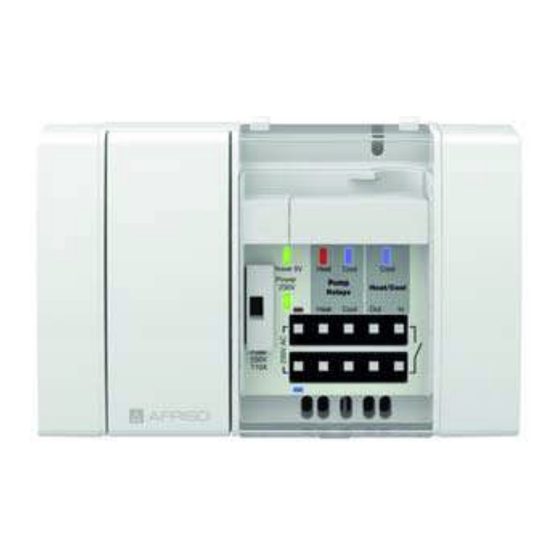
Product description Overview A. Fuse compartment B. Operation mains voltage (LED green) C. Operation 5 V (LED green) D. Pump Heating (LED red) E. Pump Cooling (LED blue) F. Cooling (LED blue) G. Input switchover Heating/ Cooling H. Cascading output Heat- ing/Cooling I. -
Page 8: Application Examples
Product description Dimensions 140 mm 122 mm Application example(s) Figure 1: Base module, controller module, timer module, room temperature sensors D and actuators... - Page 9 Product description Figure 2: Base module, controller module F , timer module, room temperature sen- sors F, external antenna and actuators Figure 3: Base module with wireless module for timer module and external antenna...
-
Page 10: Technical Specifications
Product description Function CosiTherm® is a single room temperature controller used to control the tem- perature in rooms with underfloor heating system (heat/cool). The base mod- ule is the central component of CosiTherm®. The controller modules can be connected to the product. The product supplies the room temperature sensors D with 5 V DC and the thermal actuators with 230 V AC via the controller modules. - Page 11 Product description Parameter Value Supply voltage Nominal voltage AC 230 V, 50 Hz to 60 Hz Nominal power 1 VA (base module only) Mains fuse T 10 A Relay load Max. 230 V, max. 2 A, power factor > 0.6 Permissible H03 VV-H2-F 2 x 0.75 mm²...
- Page 12 Product description Information on CosiTherm® as per DIN EN 60730-1:2017-05 • CosiTherm® is an electronic control type C as per EN 60730-1. • CosiTherm® is suitable for continuous operation. • The type of disconnection of the actuators and pumps is micro disconnec- tion.
-
Page 13: Installation Site
Mounting Mounting Installation site The product (CosiTherm®) must be mounted in the vicinity of the heating cir- cuit manifold. Mounting the product Verify that the product is disconnected from mains. 1. Open the cover using a screwdriver. 2. Pull off the end cover. - Page 14 Mounting 3. Connect the controller module(s) to the product module and secure with the catch. 4. Refit the end cover onto the last controller module.
- Page 15 Mounting 5. Refit the cover and close...
-
Page 16: Electrical Connection
Mounting Electrical connection DANGER ELECTRIC SHOCK • Verify that the degree of protection against electric shock (protection class II, double insulation) is not reduced by the type of electrical installation. Failure to follow these instructions will result in death or serious injury. DANGER ELECTRIC SHOCK CAUSED BY LIVE PARTS •... -
Page 17: Connection Diagram
Mounting 5.3.1 Connection diagram A. 230 V AC supply B. Input Heating/Cooling Open: Heating Closed: Cooling Internal control voltage: 5 V DC C. Cascading output Voltage-free relay contact Max. 250 V AC, 3 A Max. 30 V DC, 3 A D. - Page 18 Mounting 5.3.3 Fitting the cable clamp 1. Fix the cable at the rear of the controller module using the cable clamp (A). If room temperature sensors with a wired connection are used, first make the electrical connection of the room tempera- ture sensors and then fit the cable clamp.
- Page 19 Mounting 2. Repeat this procedure for all other cables. 3. It is possible to open the cable clamps. To do so, pull the two tabs (2) outwards and remove the cable clamp. Mounting modules on a DIN rail Verify that all modules (base module and controller modules) are plugged together and firmly locked.
- Page 20 Mounting Removing modules from a DIN rail 1. Slightly lift the modules (base module and controller modules) and tilt the top away from the DIN rail. 2. Remove the modules (base mod- ule and controller modules) towards the bottom.
-
Page 21: Electrostatic Discharge
Mounting Retrofitting a wireless module for a timer module NOTICE ELECTROSTATIC DISCHARGE • Always earth yourself before touching electronic components. • Do not touch the product to plug it in; use the anti-electrostatic film to plug the product into the slot. Failure to follow these instructions can result in equipment damage. - Page 22 Mounting 3. Refit the cover until it snaps in. 4. Mount the antenna to the wireless module for timer module as shown. Mounting an external antenna 5.7.1 Adhesive antenna Transmission power gain: 2 dbi...
- Page 23 Mounting 1. Open/remove the cover of the cabinet. 2. Drill a hole into the inside of the cabinet using a power drill. 3. Route the cable through the drilled hole and screw the connec- tion of the adhesive antenna to the wireless module for timer module.
- Page 24 Mounting 5.7.2 Antenna angular SMA connector and coaxial cable Transmission power gain: 3.5 dbi 1. Open/remove the cover of the cabinet. 2. Drill a hole into the cover of the cabinet using a power drill.
- Page 25 Mounting 3. Screw one end of the coaxial cable to the wireless module for timer module. 4. Remove the nut at the other end of the coaxial cable and push the connection through the drilled hole. 5. Fit the nut from the outside. 6.
-
Page 26: Operation
Operation Operation Overview of the LED signals C D E Display State Explanation Operation Solid lit When 230 V AC mains voltage is applied mains voltage Goes off In the case of power failure (LED green) If the fuse (1) trips Operation 5 V Solid lit If 5 V supply is applied... -
Page 27: Maintenance
Maintenance Maintenance The product is maintenance-free. Troubleshooting Any malfunctions that cannot be removed by means of the measures described in this chapter may only be repaired by the manufacturer. Problem Possible reason Repair LED operation mains No mains voltage Check the supply volt- voltage not lit (green LED) Fuse defective... -
Page 28: Troubleshooting
Troubleshooting 2. Remove the fuse holder. 3. Replace the defective fuse with a fuse of the same type. 4. Insert the fuse holder into the fuse compartment. 5. Close the cover. -
Page 29: Decommissioning / Disposal
Decommissioning, disposal Decommissioning, disposal Dispose of the product in compliance with all applicable directives, standards and safety regulations. Electronic components must not be disposed of together with the normal household waste. 1. Disconnect the product from mains. 2. Dismount the product (see chapter "Mounting", reverse sequence of steps). -
Page 30: Spare Parts And Accessories
Spare parts and accessories Spare parts and accessories Product designation Part no. Figure Timer module "UM" 78113 Wireless module for timer 78121 module "FM" Adhesive antenna 78175 Magnetic foot antenna 78167 Antenna angular SMA con- 78168 nector and coaxial cable... - Page 31 Information on EnOcean® wireless Information on EnOcean® wireless 13.1 Range of EnOcean® wireless Visit www.enocean.com for further information on range planning with EnOcean®. 13.2 Additional information on EnOcean® wireless systems Additional information on planning, installation and operation of EnOcean® wireless systems can be found at www.enocean.com. •...
- Page 32 Appendix Appendix 14.1 EU Declaration of Conformity...
Need help?
Do you have a question about the CosiTherm Series and is the answer not in the manual?
Questions and answers