Sign In
Upload
Download
Add to my manuals
Delete from my manuals
Share
URL of this page:
HTML Link:
Bookmark this page
Add
Manual will be automatically added to "My Manuals"
Print this page
×
Bookmark added
×
Added to my manuals
Manuals
Brands
Panasonic Manuals
Digital Camera
DC-BS1HPP
Service manual
Panasonic DC-BS1HPP Service Manual
Hide thumbs
1
2
3
4
5
6
7
8
9
10
11
12
13
14
15
16
17
18
19
20
21
22
23
24
25
26
27
28
29
30
31
32
33
34
35
36
37
38
39
40
41
42
43
44
45
46
47
48
49
50
51
52
53
page
of
53
Go
/
53
Bookmarks
Advertisement
Quick Links
Download this manual
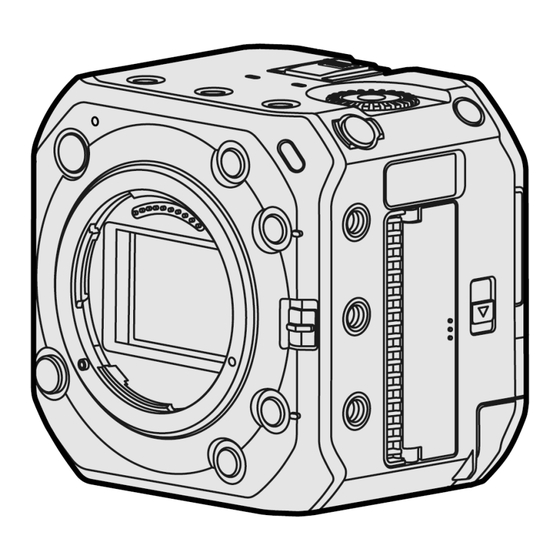
DC-BS1HPP
Model No.
DC-BS1HE
DC-BS1HEE
DC-BS1HGC
DC-BS1HGD
DC-BS1HGK
DC-BS1HGW
Colour
Black Type
© Panasonic Corporation 2021 Unauthorized copying and
distribution is a violation of law.
Order No.DSC2111007CE
B26
Digital Camera
Previous
Page
Next
Page
1
2
3
4
5
Advertisement
Need help?
Do you have a question about the DC-BS1HPP and is the answer not in the manual?
Ask a question
Questions and answers
Related Manuals for Panasonic DC-BS1HPP
Digital Camera Panasonic DC-BGH1 Operating Instructions Manual
(284 pages)
Digital Camera Panasonic DC-BGH1 Operating Instructions Manual
(108 pages)
Digital Camera Panasonic Basic DC-BGH1 Operating Instructions Manual
(24 pages)
Digital Camera Panasonic DC-BGH1 Owner's Manual
(96 pages)
Digital Camera Panasonic Lumix DC-BS1H Operating Instructions Manual
(304 pages)
Digital Camera Panasonic DC-BS1H Operating Instructions Manual
(24 pages)
Digital Camera Panasonic DC-BS1H Operating Instructions Manual
(112 pages)
Digital Camera Panasonic DC-BS1H Owner's Manual
(100 pages)
Digital Camera Panasonic DC-BS1HE Service Manual
(53 pages)
Digital Camera Panasonic LUMIX DC-FZ80 Owner's Manual
(311 pages)
Digital Camera Panasonic lumix DC-TZ90 Operating Instructions Manual
(302 pages)
Digital Camera Panasonic Lumix DC-ZS70 Basic Owner's Manual
(72 pages)
Digital Camera Panasonic Lumix DC-ZS70K Owner's Manual
(302 pages)
Digital Camera Panasonic Lumix DC-ZS200 Owner's Manual
For advanced features (308 pages)
Digital Camera Panasonic Lumix S5 Manual
(570 pages)
Digital Camera Panasonic Lumix S5 Operating Instructions Manual
(196 pages)
This manual is also suitable for:
Dc-bs1he
Dc-bs1hee
Dc-bs1hgc
Dc-bs1hgd
Dc-bs1hgk
Dc-bs1hgw
Print
Rename the bookmark
Delete bookmark?
Delete from my manuals?
Login
Sign In
OR
Sign in with Facebook
Sign in with Google
Upload manual
Upload from disk
Upload from URL


Need help?
Do you have a question about the DC-BS1HPP and is the answer not in the manual?
Questions and answers