Advertisement
Quick Links
Advertisement

Related Manuals for ABB ACS-BP-S


Summary of Contents for ABB ACS-BP-S
- Page 1 — ABB INDUSTRIAL DRIVES ACS-BP-S Basic control panel User's manual...
- Page 3 ACS-BP-S Basic control panel User's manual Table of contents 3AXD50000032527 Rev B Original instructions EFFECTIVE: 2024-09-16...
- Page 5 Table of contents 5 Table of contents 1 Introduction Applicability ....................... Safety .......................... Related manuals ....................... Attach and remove the control panel ..............2 Start-up and use Start up ........................Control panel use ...................... Display ........................The Options menu ....................Start and stop the drive ..................
- Page 6 6 Table of contents Cyber security disclaimer ................Further information...
- Page 7 Introduction 7 Introduction Applicability This manual is applicable with the ACS-BP-S basic control panel, the panel software version GPBPS v1.2 and later software versions. The images and instructions are based on the use of control panel with an ACS580 drive equipped with the Standard control program version 1.6. Note that there may be differences if you use the basic control panel with other equipment or program versions.
- Page 8 8 Introduction ACS580-04 drive modules (200 to 500 kW) 3AXD50000015497 hardware manual ACS580-04 drive modules (200 to 500 kW) 3AXD50000015469 quick installation and start-up guide ACS380 hardware manual 3AXD50000029274 Drive firmware manuals and guides ACS580 standard control program firmware 3AXD50000016097 manual ACS380 machinery control program firmware 3AXD50000029275...
- Page 9 Start-up and use 9 Start-up and use Start up To start up the drive, you need to set the motor data, motor control, connection macro and drive parameters. See the relevant drive firmware manual for start-up details. Control panel use Clip - press down to remove the panel.
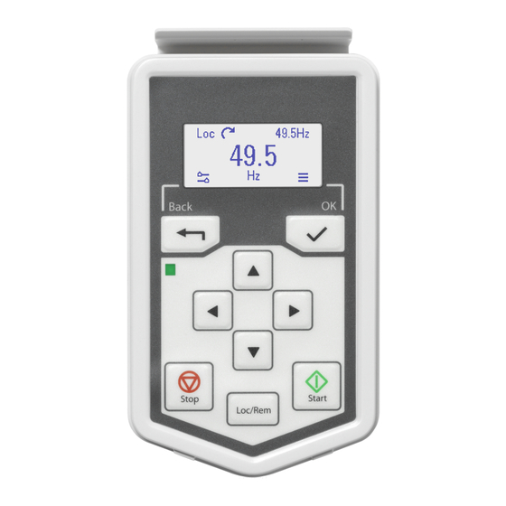
- Page 10 10 Start-up and use Display Options menu The Back button: opens the Options menu Currently monitored value: actual Rotation direction: forward or reverse Currently monitored value: reference The OK button: opens the Main menu The Options menu Reference speed or frequency Rotation direction - forward or reverse Active faults Active warnings...
- Page 11 Start-up and use 11 Press the arrow buttons to set the speed or frequency. Press the OK button to confirm the change. Change the rotation direction In the Options menu , move the rota- tion direction item vith the arrow but- tons.
- Page 12 12 Start-up and use Open diagnostics from the Home Open the Main menu view. Scroll to Diagnostics and press the OK button to open the submenu. Select the warning or fault list with the arrow button and press the OK button. See the relevant drive firmware manual for the related warnings and faults.
- Page 13 The main menu structure 13 The main menu structure The Main menu Motor data - motor parameters Motor control - motor behavior settings Control macros - presetting for I/O set- tings and fieldbus Diagnostics - faults, warnings, fault log and connection status Energy efficiency - energy savings Backup and restore Parameters...
- Page 14 Stop mode - Coast, DC hold, Ramp Acceleration time Deceleration time Maximum allowed speed/frequency Maximum allowed current Minimum allowed speed/frequency Connection macros The connection macros available depend on the drive type ABB Standard (2-wire) 3-wire ABB Standard Vector Alternate Motor potentiometer Hand/Auto Hand/PID 10. Panel/PID...
- Page 15 The main menu structure 15 Diagnostics Active Fault - if there is an active fault, the fault code is displayed Fault History - list of latest fault codes (newest first) Active Warning - if there is an active warning, the warning code is displayed I/O status - I/O settings For information about the fault and warning codes, see the drive firmware manual.
- Page 17 Troubleshooting 17 Troubleshooting Fault and warning messages A fault message The display shows a fault message code if a problem has been detected. A fault message needs your immediate attention. When a fault message code is displayed: Identify and eliminate the cause. The fault codes are listed in the drive firm- ware manual.
- Page 18 18 Troubleshooting Drive and panel communication failure There is a general communication failure, e. g., the drive does not respond to the panel commands. The drive and panel are not compatible, e. g., the drive does not support the basic panel. Status light Green, continuous The drive is functioning nor-...
- Page 19 Technical data 19 Technical data Components COMPONENT DATA DETAILS Connector RJ-45 female connector. If a cable is used for the drive connection, the maximum length is 100 meters (328 ft.) When using cables over 10 meters (33.8 ft.) long, it is re- commended to use the CDPI- 01 with termination switch off.
- Page 20 20 Technical data Degree of protection Attached to a drive IP55 Separately IP20 Control panel as stand-alone connected to IP20 RJ45 cable Control panel mounted to DPMP-01 IP55 Control panel mounted to DPMP-02 or -03 IP65 Dimensions Materials Enclosure PCB/ABS Packaging Cardboard Screen...
- Page 21 ABB and its affiliates are not liable for damages and/or losses related to such security breaches, any unauthorized access, interference, intrusion, leakage and/or...
- Page 23 Product and service inquiries Address any inquiries about the product to your local ABB representative, quoting the type designation and serial number of the unit in question. A listing of ABB sales, support and service contacts can be found by navigating to www.abb.com/contact-centers.
- Page 24 3AXD50000032527B © Copyright 2024 ABB. All rights reserved. Specifications subject to change without notice.
Need help?
Do you have a question about the ACS-BP-S and is the answer not in the manual?
Questions and answers