
Related Manuals for Cooking Performance Group 351OCB16I

Summary of Contents for Cooking Performance Group 351OCB16I
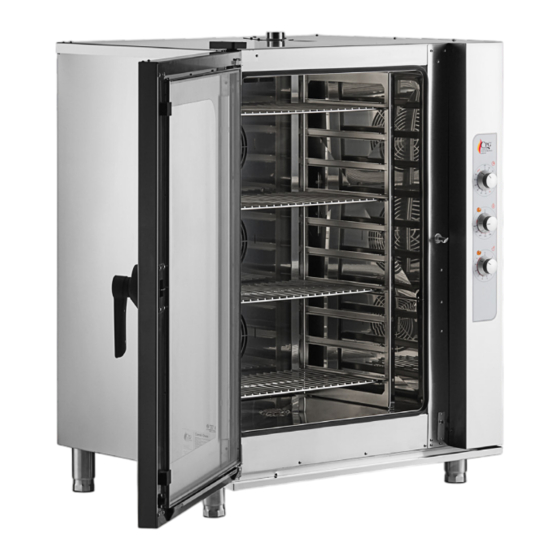
- Page 1 Service Manual Electric Combi Ovens with Manual Controls 351OCB16I, 351OCB110I, 351OCB26I, 351OCB210I REVISED 7/2024 www.cookingperformancegroup.com...
-
Page 2: Table Of Contents
Wiring Diagrams - 351OCB16I . . . . . . . . . . . . . . . . . . -
Page 3: Troubleshooting
Service Manual Troubleshooting PROBLEM CAUSE RESOLUTION The oven has no power (cool- No power input . Check building breaker/power . ing fans/LED door light do not Incorrect connection to main power . Check connection from oven to building power . come on with timer on) . -
Page 4: Water Quality
Steam Table Pan Size Ovens . Please review the model number details on the Oven Information Label to see which oven you have . The steam table pan size units are 351OCB16I & 351OCB110I . The full size pan ovens are 351OCB26I & 351OCB210I . -
Page 5: Steam Table Pan Size Ovens
Service Manual Steam Table Pan Size (Back) Fig. 4A Fig. 4B 1 . Loosen the hose clamp at the rear drain elbow and remove the hose and elbow from the unit (Fig . 4A) . 2 . Remove the phillips head screws around the Hose Clamp perimeter of the back panel . -
Page 6: Part Testing
Service Manual Part Testing Fig. 10 Fig. 11 Fuses 1 . With power disconnected, open the fuse holders by pulling down firmly on the tab with the label. The fuse holding area will rotate downward (Fig 10) . 2 . Remove the fuse (Fig 11). 3 . -
Page 7: Microswitch
Service Manual Part Testing Fig. 14 Fig. 15 Door Microswitch 1 . Remove the (2) phillips screws from the switch mounting plate (Fig. 14). 2 . Remove the switch. Remove its (2) leads, noting their position on the switch (Fig 15) . 3 . -
Page 8: Fan Motor Capacitors
(Fig . 19) and list below . The element resistances between oven models are as follows: Fig. 19 Fig. X 351OCB16I & 351OCB26I & 351OCB110I 351OCB210I - Contacts 1-6 = 32 .4 ohms 26 .1 ohms - Contacts 2-5 = 32 .5 ohms... -
Page 9: Linear Timer
Service Manual Part Testing Linear Timer Fig. 20 1 . The linear timer is located behind the top knob of the control panel (Fig . 20) . 2 . With power off, check for continuity as described below: -From 1 to 3 - continuity with timer at "0" -From 1 to 3 - no continuity with timer set above "0"... -
Page 10: Humidification Regulator
Service Manual Part Testing Humidification Regulator 1 . The humidification (steam) regulator is behind the bottom knob on Fig. 23 the control panel . The thermostat probe is in the oven on the righthand side (Fig . 23) . 2 . With the oven off and cold and the knob set to "0", check for continuity as described below: -From P1 to 2 - continuity -From P2 to 4 - continuity... -
Page 11: Indicator Lights
Service Manual Part Testing Indicator Lights For Thermostat Indicator Light: Fig. 26 -With the oven on, turn the thermostat above the current chamber temperature . If there is input voltage (208v or 240v) to the indicator light but the light does not come on, replace it . For Humidification Indicator Light: -With the oven on, turn the humidification knob above the current setting . -
Page 12: Parts Replacement
Service Manual Part Replacement DISCONNECT ELECTRICITY BEFORE CONTINUING . COMPONENTS OF OVEN Fuse Holders & Fuses Fuses Only: Fig. 30 Fig. 31 1 . Open the fuse holders by pulling down firmly on the tab with the label (Fig . 30 & 31) . The fuse holding area will rotate downward . -
Page 13: Contactors - Heating Elements
Service Manual Part Replacement DISCONNECT ELECTRICITY BEFORE CONTINUING . COMPONENTS OF OVEN Contactors - Heating Elements 1 . Disconnect the leads going to and from the contactor, noting their positions (Fig . 36) . Fig. 36 2 . Push down on the top of the contactor and rotate the bottom of it away from the sheet metal it attaches to (Fig . -
Page 14: Fan Motors & Capacitors
Service Manual Part Replacement DISCONNECT ELECTRICITY BEFORE CONTINUING . COMPONENTS OF OVEN Fan Motors Fig. 41 1 . Inside the oven, remove oven racks. Remove the sheet grids by lifting them up at the bottom and rotating the bottom toward the middle of the oven until they clear the metal pins at the top and bottom of the oven (Fig . -
Page 15: Heating Elements
Service Manual Part Replacement DISCONNECT ELECTRICITY BEFORE CONTINUING . COMPONENTS OF OVEN Heating Elements 1 . Remove the back panel of the oven, and remove the Fig. 46 leads connected to the element (Fig . 47) . 2 . Inside the oven, remove oven racks. Remove the sheet grids by lifting them up at the bottom and rotating the bottom toward the middle of the oven until they clear the metal pins at the top and bottom of the oven . -
Page 16: Chamber Thermostat
Service Manual Part Replacement DISCONNECT ELECTRICITY BEFORE CONTINUING . COMPONENTS OF OVEN Chamber Thermostat 1 . Inside the oven, remove the righthand sheet grid to access the thermostat probe. Using fingers or a Fig. 52 Fig. 54 screwdriver, relase the probe end from the mounting clips on the wall (Fig . -
Page 17: Humidification Regulator
Service Manual Part Replacement DISCONNECT ELECTRICITY BEFORE CONTINUING . COMPONENTS OF OVEN Humidification Regulator 1 . Remove the bottom knob from the front of the control panel Fig. 56 Fig. 57 by pulling it straight off its shaft (Fig . 56) . 2 . -
Page 18: Indicator Lights
Service Manual Part Replacement DISCONNECT ELECTRICITY BEFORE CONTINUING . COMPONENTS OF OVEN Indicator Lights 1 . Disconnect the leads from the light, noting their position (Fig . 62) . Fig. 62 Fig. 63 2 . Work the light out by depressing the tabs on the body of the light and pushing them out through the front of the control panel (Fig . -
Page 19: Door Handle
Service Manual Part Replacement DISCONNECT ELECTRICITY BEFORE CONTINUING . COMPONENTS OF OVEN Door Handle 1 . Inside the door, remove the (4) phillips screws from the latch cover plate (Fig . 66) . 2 . With the cover plate off, hold the handle on the outside of the door. -
Page 20: Oven Door Assembly
Service Manual Part Replacement DISCONNECT ELECTRICITY BEFORE CONTINUING . COMPONENTS OF OVEN Oven Door Assembly 1 . Slide the clips for the inner glass outward . 2 . Swing the inner glass away fro the door assembly . 3 . At the top and bottom of the inner glass, swing the hinge pins out of their plastic clips. -
Page 21: Wiring Diagrams - 351Ocb16I
Service Manual Wiring Diagram - 351OCB16I black LEGEND: MO = Main terminal block Capacitor DB = Door button MS = Wago connector Oven light Neutral GND = Ground Cam programmer GS = Power supply = Electrical resistance FH = Fuse holder... - Page 22 Service Manual Wiring Diagram - 351OCB16I 208V - 240V 3 BLACK BLACK UPPER ELECTRICAL R(2) RESISTANCE BLACK BLACK LOWER ELECTRICAL R(1) RESISTANCE LEGEND: MO = Main terminal block Capacitor DB = Door button MS = Wago connector Oven light Neutral...
- Page 23 Service Manual Wiring Diagram - 351OCB16I COMPONENTS (rear view): R(2) M(2) R(1) M(1) Filename: Rev. 52SCE00310 LEGEND: MO = Main terminal block Capacitor DB = Door button MS = Wago connector Oven light Neutral GND = Ground Cam programmer GS = Power supply...
-
Page 24: Parts Diagrams - 351Ocb16I
TERMHOSTAT BULB SPRING CLIP mechanical version 020SON0001 TEMPERATURE PROBE touch/digital version 020MOT0032 MOTOR 220V 040GUA00007 CHAMBER PROBE FLANGE GASKET touch/digital version Parts Diagram - 351OCB16I Item # Description Part # Air Deflector Contact Mfr Rev. Rev.Date Rev.Description Revised by Designed by:... - Page 25 30TBG00004 HT DETERGENT PIPE 8X15 BLUE (HUMIDIFICATION) 2m (78"74) 020CND00009 CAPACITOR 6 µF 40CER00001 TOP HINGE SQ RAL7016 Parts Diagram - 351OCB16I 40CER00002 TOP HINGE COVER SQ RAL7016 40DIS00011 CONDENSATE TRAY OVEN SIDE SUPPORT 30TBG00001 SILICORD PIPE Ø30X38 0,05m (1"97)
- Page 26 Service Manual SPARE CODE DESCRIPTION Q.TY PART No 51FRO00129 FRONT LABEL DESIGN 40MAN00015 KNOB Parts Diagram - 351OCB16I 020LSP0004 DASHBOARD INDICATOR LAMP 230V ORANGE 020TMR0001 LINEAR TIMER 020TER0001 CHAMBER THERMOSTAT 20REG00009 ENERGY REGULATOR COD. 5057021010 020SCH0016 BUZZER ELECTRONIC BOARD Link?:...
- Page 27 SQUERO HANDLE 85VAS00060 INTERNAL GLASS TRAY SQUERO 20PPC00028 PA 6.6 CABLE LEAD Ø8.4 60MGNSN002 MAGNET FOR SENSOR Parts Diagram - 351OCB16I 85CER00048 INTERNAL GLASS SPRINGS LOCKING SYSTEM 50PAR00037 CABLE/PIPE CLAMP Ø 6 020LED0002 LED LIGHT PT 4T CR380OP4 L=565mm 85AVE00139* SQ06 EXTERNAL GLASS ASSY Rev.
-
Page 28: Wiring Diagrams - 351Ocb26I
Service Manual Wiring Diagram - 351OCB26I LEGEND: BLACK MO = Main terminal block Capacitor DB = Door button MS = Wago connector Oven light Neutral GND = Ground Cam programmer GS = Power supply = Electrical resistance FH = Fuse holder Solenoid valve HA = Acoustic signal Safety thermostat... - Page 29 Service Manual Wiring Diagram - 351OCB26I LEGEND: 208V - 240V 3 MO = Main terminal block Capacitor DB = Door button MS = Wago connector Oven light Neutral GND = Ground Cam programmer GS = Power supply = Electrical resistance FH = Fuse holder Solenoid valve BLACK...
- Page 30 Service Manual Wiring Diagram - 351OCB26I COMPONENTS (rear view): MC(2) R(2) R(1) MC(1) Filename: Rev. 52SCE00211 LEGEND: Capacitor MC = Cooling motor CFU = Universal female connector MO = Main terminal block CMU = Universal male connector MS = Wago connector Door button Neutral Oven light...
-
Page 31: Parts Diagrams - 351Ocb26I
70DAD00019 NUT M 8 PREVAILING TORQUE NUT SS 60VENAI013 FAN 200X61 AIRTEK 2.0 Service Manual 040BOC00006 CRANKSHAFT BUSH 20RES00042 HEATING ELEMENT 6.5KW 230V 6 COILS 10PIA00339 WATER DRAIN COVER 60MOLAI002 TERMHOSTAT BULB SPRING CLIP mechanical version 020SON0001 TEMPERATURE PROBE touch/digital version 020MOT0032 MOTOR 220V 040GUA00007... - Page 32 60NASAI001 HANDLE STUD L70MM 60PERAI003 HANDLE PIVOT RCB-RCG 020PUL0002 NO/NC MICRO SWITCH Service Manual 020TER0007 SAFETY THERMAL SWITCH 1 POLE 85GRI00273 RIGHT GRID SHEET GA-BIV 6/86 85GRI00272 LEFT SHEET GRID PA-BIV 6/86 60PIE00004 OCTAGONAL ADJUSTABLE FEET Ø64XH120 020MOR0001 TERMINAL BLOCK BRIDGE 6-16 SQM 20ELE00029 SOLENOID VALVE 90°...
- Page 33 Service Manual SPARE CODE DESCRIPTION Q.TY PART 51FRO00129 FRONT LABEL DESIGN 040MAN00011 KNOB 020LSP0004 DASHBOARD INDICATOR LAMP 230V ORANGE 020TMR0001 LINEAR TIMER 020TER0001 CHAMBER THERMOSTAT 20REG00009 ENERGY REGULATOR COD. 5057021010 85CRU00318 SQ0621A MECHANIC WELDED DASHBOARD Parts Diagram - 351OCB26I 020SCH0016 BUZZER ELECTRONIC BOARD Item # Description...
- Page 34 Service Manual SPARE CODE DESCRIPTION Q.TY PART No 85AVI00038 SQ06 INTERNAL GLASS ASSY 040TAP00015 RUBBER SPACER FOR INTERNAL GLASS 60MAG00031 SQUERO HANDLE 85VAS00060 INTERNAL GLASS TRAY SQUERO 20PPC00028 PA 6.6 CABLE LEAD Ø8.4 60MGNSN002 MAGNET FOR SENSOR 85CER00048 INTERNAL GLASS SPRINGS LOCKING SYSTEM Parts Diagram - 351OCB26I 50PAR00037 CABLE/PIPE CLAMP Ø...
-
Page 35: Wiring Diagrams - 351Ocb110I
Service Manual Wiring Diagram - 351OCB110I LEGEND: black MO = Main terminal block Capacitor DB = Door button MS = Wago connector Oven light Neutral GND = Ground Cam programmer GS = Power supply = Electrical resistance FH = Fuse holder Solenoid valve HA = Acoustic signal Safety thermostat... - Page 36 Service Manual Wiring Diagram - 351OCB110I 208V - 240V 3 UPPER BLACK ELECTRICAL R(3) RESISTANCE BLACK MIDDLE BLACK ELECTRICAL R(2) RESISTANCE BLACK LOWER BLACK ELECTRICAL R(1) RESISTANCE BLACK LEGEND: MO = Main terminal block Capacitor DB = Door button MS = Wago connector K(1) K(2) K(3)
- Page 37 Service Manual Wiring Diagram - 351OCB110I COMPONENTS POSITION: K(1) K(2) K(3) Filename: Rev. 52SCE00311 LEGEND: MO = Main terminal block Capacitor DB = Door button MS = Wago connector Oven light Neutral GND = Ground Cam programmer GS = Power supply = Electrical resistance FH = Fuse holder Solenoid valve...
-
Page 38: Parts Diagrams - 351Ocb110I
PART No 10DEF00008 AIR DEFLECTOR CP10-CP12 SQ MEC 70DAD00019 NUT M 8 PREVAILING TORQUE NUT SS Service Manual 60VENAI013 FAN 200X61 AIRTEK 2.0 040BOC00006 CRANKSHAFT BUSH 20RES00041 HEATER 5KW 230V 6 COILS 10PIA00339 WATER DRAIN COVER 60MOLAI002 TERMHOSTAT BULB SPRING CLIP 020SON0001 TEMPERATURE PROBE 020MOT0028... - Page 39 60PIE00004 OCTAGONAL ADJUSTABLE FEET Ø64XH120 85FIA00009 SIDE ASSEMBLY SX SQ06-SQ07 Service Manual 10FIA00281 RIGHT SIDE SQ06U 020MOR0001 TERMINAL BLOCK BRIDGE 6-16 SQM 20ELE00030 HUMIDIFICATION SOLENOID VALVE 10FIA00244 SQ10U MECHANIC BACK 10PIAA10SAA013 DOOR LOCK PLATE 85CER00008 OVEN DOOR LOWER HINGE SQ-CP 020MOT0009 AXIAL MOTOR 50FIL00004...
- Page 40 Service Manual SPARE CODE DESCRIPTION Q.TY PART No 51FRO00129 FRONT LABEL DESIGN 040MAN00011 KNOB 020LSP0004 DASHBOARD INDICATOR LAMP 230V ORANGE 020TMR0002 TIMER LOGARITMIC FOR LIDO/GIUDECCA Parts Diagram - 351OCB110I 020TMR0001 LINEAR TIMER 020TER0001 CHAMBER THERMOSTAT 20REG00009 ENERGY REGULATOR COD. 5057021010 020SCH0016 BUZZER ELECTRONIC BOARD Item #...
- Page 41 Service Manual SPARE CODE DESCRIPTION Q.TY PART No 85AVI00031 SQ10 INTERNAL GLASS ASSY 85AVI00037 SQ10 INTERNAL GLASS ASSY 040TAP00015 RUBBER SPACER FOR INTERNAL GLASS 60MAG00031 SQUERO HANDLE 85VAS00060 INTERNAL GLASS TRAY SQUERO 60MGNSN002 MAGNET FOR SENSOR 85CER00048 INTERNAL GLASS SPRINGS LOCKING SYSTEM 50PAR00037 CABLE/PIPE CLAMP Ø...
-
Page 42: Wiring Diagrams - 351Ocb210I
Service Manual Wiring Diagram - 351OCB210I LEGEND: BLACK MO = Main terminal block Capacitor DB = Door button MS = Wago connector Oven light Neutral GND = Ground Cam programmer GS = Power supply = Electrical resistance FH = Fuse holder Solenoid valve HA = Acoustic signal Safety thermostat... - Page 43 Service Manual Wiring Diagram - 351OCB210I LEGEND: 208V - 240V 3 MO = Main terminal block Capacitor DB = Door button MS = Wago connector Oven light Neutral GND = Ground Cam programmer GS = Power supply = Electrical resistance BLACK FH = Fuse holder Solenoid valve...
- Page 44 Service Manual Wiring Diagram - 351OCB210I COMPONENTS (rear view): MC(2) R(3) R(2) MC(1) R(1) Rev. Filename: 52SCE00213 LEGEND: Capacitor MC = Cooling motor CFU = Universal female connector MO = Main terminal block CMU = Universal male connector MS = Wago connector Door button Neutral Oven light...
-
Page 45: Parts Diagrams - 351Ocb210I
PART No 10DEF00126 DEFLECTOR SQ1021 70DAD00019 NUT M 8 PREVAILING TORQUE NUT SS Service Manual 60VENAI013 FAN 200X61 AIRTEK 2.0 040BOC00006 CRANKSHAFT BUSH 20RES00042 HEATING ELEMENT 6.5KW 230V 6 COILS 10PIA00339 WATER DRAIN COVER 60MOLAI002 TERMHOSTAT BULB SPRING CLIP mechanical version 020SON0001 TEMPERATURE PROBE touch/digital version... - Page 46 85VAS00049 ELE.SQ SOLDERED CONDENSER TRAY ASSY 040GUA00014 DOOR GASKET 3,3m (129"92) Service Manual 60NASAI001 HANDLE STUD L70MM 60PERAI003 HANDLE PIVOT RCB-RCG 020PUL0002 NO/NC MICRO SWITCH 020TER0007 SAFETY THERMAL SWITCH 1 POLE 10GRI00304 LEFT SHEET GRID GA-BIV 10/85 10GRI00305 RIGHT GRID SHEET GA-BIV 10/85 60PIE00004 OCTAGONAL ADJUSTABLE FEET Ø64XH120 020MOR0001...
- Page 47 Service Manual SPARE CODE DESCRIPTION Q.TY PART No 51FRO00129 FRONT LABEL DESIGN 040MAN00011 KNOB 020LSP0004 DASHBOARD INDICATOR LAMP 230V ORANGE 020TMR0002 TIMER LOGARITMIC FOR LIDO/GIUDECCA 020TMR0001 LINEAR TIMER Parts Diagram - 351OCB210I 020TER0001 CHAMBER THERMOSTAT 20REG00009 ENERGY REGULATOR COD. 5057021010 85CRU00326 SQ1021A MECH.WELDED DASHBOARD 020SCH0016...
- Page 48 Service Manual SPARE CODE DESCRIPTION Q.TY PART No 85AVI00031 SQ10 INTERNAL GLASS ASSY 85AVI00037 SQ10 INTERNAL GLASS ASSY 040TAP00015 RUBBER SPACER FOR INTERNAL GLASS 60MAG00031 SQUERO HANDLE 85VAS00060 INTERNAL GLASS TRAY SQUERO 60MGNSN002 MAGNET FOR SENSOR 85CER00048 INTERNAL GLASS SPRINGS LOCKING SYSTEM 50PAR00037 CABLE/PIPE CLAMP Ø...
Need help?
Do you have a question about the 351OCB16I and is the answer not in the manual?
Questions and answers