Table of Contents
Advertisement
Quick Links
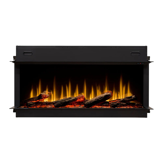
Installation and User's Guide
We value your feedback!
Your input helps to create even better products and experiences.
Share the warmth and leave a review.
dimplex.com/sharethewarmth
@DimplexNorthAmerica
IMPORTANT SAFETY INFORMATION:
Read this manual first before attempting to install or use this electric fireplace. Always comply with the
warnings and safety instructions contained in this manual to prevent personal injury or property damage.
To view the full line of Dimplex products, visit www.dimplex.com
INSTALLER: LEAVE THIS MANUAL WITH THE APPLIANCE.
CONSUMER: RETAIN THIS MANUAL FOR FUTURE REFERENCE
Models
ULT50-AM
ULT60-AM
ULT74-AM
ULT88-AM
ULT100-AM
Certified to:
UL 2021, 4th
Ed.
7216840100R01
Advertisement
Table of Contents


Need help?
Do you have a question about the IGNITE ULTRA ULT50-AM and is the answer not in the manual?
Questions and answers