
Related Manuals for EI Ei1000G

Summary of Contents for EI Ei1000G
- Page 1 The Gateway Ei1000G Installation Manual Read and retain carefully for as long as the product is being used. It contains vital information on the operation and installation. The manual should be regarded as part of the product.
- Page 3 Contents Page Introduction Product Overview Technical Specifications Important Safety Instructions Locating your Gateway Installation Gateway System Set Up Testing Troubleshooting Guarantee Contact us...
- Page 4 1. Introduction An exciting innovation in home life safety, the Ei1000G Gateway will connect to compatible alarms and HomeLINK Environmental Sensors to push data to the HomeLINK Dashboard and App for Residents. The data from connected devices allows clients to view and manage their installed alarms and sensors and provides information on Fire and CO activations along with actionable insights into enviromental risks including Damp and Mould, Indoor Air Quality, Excess Cold and Heat and Heat Loss.
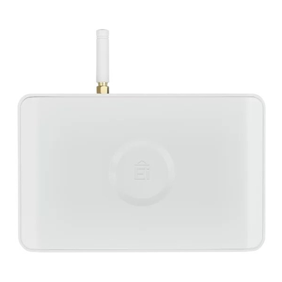
- Page 5 2. Product Overview House Off / On Test Reset Code On / Off battery switch Antenna To unclip the Gateway from the mounting plate, insert a screw driver in to the slot shown above Cellular network LED RF LED and push the Gateway upwards House Code button Test button Power LED...
- Page 6 3. Technical Specifications Supply Voltage: 230V AC, 50Hz Battery back-up: Rechargeable battery Power consumption: 40mA RF frequency: 868MHz band (1% duty cycle) RF power: 5.1 dBm (radiated) RF Range: >100 Metres in free air RF Protocol type: Mesh/Star architecture SmartLINK, HomeLINK and RadioLINK + RF Protocol: RF System size: Up to 12 RF devices...
- Page 7 4. Important Safety Instructions WARNING: Mains operated devices should be installed by a qualified electrician in accordance with the local appropriate Regulations for Electrical Installations. Failure to install the Gateway correctly may expose the user to shock or fire hazards and damage the device. ATTENTION: The device must be continuously powered 24 hours a day so it is important that it is not on a circuit that can be turned off by a switch.
- Page 8 5. Locating Your Gateway To identify a suitable location for the installation of your Gateway, we recommend you first perform a short cellular survey as follows: 1) Move the Battery Switch (see figure 1) to the “On” position. (DO NOT CONNECT TO THE MAINS SUPPLY at this stage) . ATTENTION: Do not leave your Gateway on battery power only for longer than 72 hours.
- Page 9 It is also equally important that the Gateway communicates with the RF devices installed in the dwelling. The number of walls, ceilings and metal objects in the signal path will reduce the strength of the RF signals. Do not mount your Gateway in a steel box or close to large metal objects such as boilers, as this will reduce your cellular network signal strength and will affect RF communication.
- Page 10 WARNING: Wiring must be installed in compliance with local regulations. 4. Slide the Gateway onto the mounting plate. 5. Connect the mains power to the circuit used. 6. Check that the green power LED on the Gateway is on. On power up, the blue LED and Yellow LED will also flash for a short period (<1 min). On stand by, only the green LED is on.
- Page 11 7. Gateway System Set Up Do not start the system set up until the Gateway is in Standby mode. To set up a Gateway system, simply follow the ® steps in the SmartLINK App available to download from the Google Play or iTunes app store. If you do not have log-in details for the SmartLINK App and you will be managing the system, you will need to complete the registration form available on the following link https://www.aico.co.uk/ gateway-subscription/ or by scanning the QR code on the left.
- Page 12 6) Under the Events tab, “Button Test” or “Head Removed” will be listed with the corresponding date and time; confirming that the event information is stored on the Cloud server. 7) If an Environmental Sensor was removed to generate the event, refit the Environmental Sensor and ensure that a ‘Power Up’...
- Page 13 Ei Electronics guarantees this Gateway for five years from the date of purchase against any defects that are due to faulty materials or workmanship. If this device should become defective within the guarantee period, we shall at our discretion repair or replace the faulty unit.
- Page 14 0889 Hereby, Ei Electronics declares that this Ei1000G Gateway is in compliance with the essential requirements and other relevant provisions of Directive 2014/53/EU. The Block E1 Declaration of Conformity may be consulted at www.eielectronics.com/compliance The crossed out wheelie bin symbol that is on your product indicates that this product should not be disposed of via the normal household waste stream.
- Page 16 Contact Us Aico Ei Electronics Maesbury Road Shannon Industrial Estate, Oswestry Shannon, V14 H020, Co. Clare, Ireland. Shropshire SY10 8NR Telephone: +353 (0)61 471277 Telephone: 01691 664100 www.eielectronics.com www.aico.co.uk © Ei Electronics 2024 P/N B20705 Rev1...
Need help?
Do you have a question about the Ei1000G and is the answer not in the manual?
Questions and answers