Table of Contents
Advertisement
Quick Links
SmartLINK Gateway
Ei1000G
Installation Manual
Read and retain carefully for as long as the product is being used. It contains vital information on the operation
and installation. The leaflet should be regarded as part of the product.
If you are just installing the unit, the leaflet MUST be given to the householder. The leaflet is to be given to
any subsequent user.
1
Advertisement
Table of Contents

Related Manuals for EI SmartLINK Ei1000G

Summary of Contents for EI SmartLINK Ei1000G
- Page 1 SmartLINK Gateway Ei1000G Installation Manual Read and retain carefully for as long as the product is being used. It contains vital information on the operation and installation. The leaflet should be regarded as part of the product. If you are just installing the unit, the leaflet MUST be given to the householder. The leaflet is to be given to any subsequent user.
-
Page 3: Table Of Contents
Contents Page Introduction Overview Gateway Installation Locating your Gateway SmartLINK App installation process App download and setup App and system login Property information Scan gateway Add a device What if I don’t have a QR code on my device? Seal and upload the system Additional Features Gateway signal check View system data... -
Page 4: Introduction
1. Introduction The following information is aimed at providing guidance on how to correctly install Ei Electronics Alarms in a Gateway System via the SmartLINK installation App. It is necessary to use the app to push the correct installation data to the ‘SmartLINK Cloud Portal’. - Page 5 Panel / Icon Overview House Off / On Antenna Code Test Reset On / Off battery switch Antenna GSM LED RF LED House Code button Test button Power LED Reset button...
- Page 6 SmartLINK Add in SmartLINK compatible devices for a fully cloud connected system Simply plug in Ei3000MRF Install the Gateway to Setup the Cloud portal to deliver SmartLINK modules for provide communication to - Live monitoring of connected wireless interconnection the SmartLINK Cloud Portal SmartLINK Alarm systems between Alarms and - Details of system installations...
-
Page 7: Gateway Installation
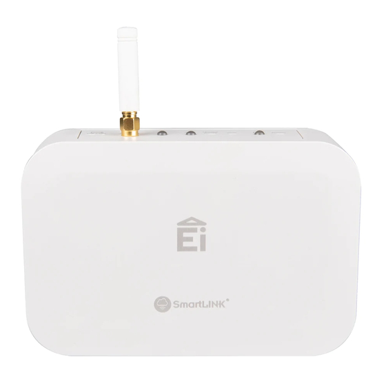
3. Gateway Installation GSM Signal Strength Test: Prior to installing your Gateway, we recommend that you perform a short GSM survey with the Gateway to ensure the location you plan to mount the Gateway in is suitable. You can do this without applying mains power to the Gateway, simply turn on the Battery Switch located at the top of the Gateway (see figure 1) and attach the Antenna, (located in the bag supplied) by rotating the gold nut clockwise and ensuring it is tightened fully in place by hand. -
Page 8: Locating Your Gateway
4. Locating Your Gateway Please mount your Gateway in a suitable location. We recommend your Gateway is mounted on a wall, in a hallway, or another suitable area provided you have sufficient GSM signal strength. Please ensure your Gateway is mounted with the Antenna in the vertical orientation. Consideration should be given to the location of the Gateway to avoid any unnecessary interaction with the Gateway once installed. - Page 9 Warning: Wiring must be installed in compliance with local regulations. Warning: This product should only be installed in a location where an all-pole mains switch in accordance with Annex L of EN62368-1 is incorporated in the electrical installation of the building.
-
Page 10: Smartlink App Installation Process
5. SmartLINK App Installation Process Install and wire your Alarms as normal following the relevant instruction manuals. App Download and Set up Download the SmartLINK app from the Google Play or iTunes app store. Step 1: App and System Login In order to log into the App, you will need to be set up on the SmartLINK Cloud Portal as an official installer linked to the Client you are undertaking the work for. -
Page 11: Property Information
Step 2: Property information Once logged select ‘Add Installation’ from the main menu and proceed to input the property details. If you use UPRNs you should input the relevant UPRN (Unique Property Reference Number) I/D for this property. The app uses an auto lookup address feature. Type in the postcode for the property and press ‘Search’. You will be presented with the actual address or a list of addresses related to that postcode. -
Page 12: Scan Gateway
Step 3: Scan Gateway Once you start the installation process the first step is to scan the Gateway prior to scanning or installing any other device, this can be done by scanning the QR code label located on the underside of the Gateway. Press ‘Scan’... -
Page 13: Add A Device
Step 4: Add a device To add a device simply click the ‘Add Unit’ button and follow the on screens instructions. If your Alarm and RF Module have a QR code label you can press the ‘Scan’ button and scan firstly the RF module label followed secondly by the Alarm / device model label. - Page 14 Number of blue flashes Models per device Ei160e Series Ei2110e Ei208 Series Ei650 / 603 Series Ei1000G Gateway Ei3014, 3016, 3018, 3024 Ei3028 Repeat Step 4 for each device you want to add to the system. Each unit’s blue LED should flash once for every unit in House Code, including the Gateway, with the exception of the Ei3028, which has two flashes, due to its ability to detect both Carbon Monoxide and Fire.
-
Page 15: What If I Don't Have A Qr Code On My Device
Step 4A: What if I don’t have a QR code on my device? Even if your device does not have a QR code label you can still use the installation app to set up your Gateway system. Just click on the ‘Skip’ button to take you to the next page. Here you will be asked to fill in the device location along with the device ‘Model’... -
Page 16: Seal And Upload The System
Step 5: Seal the system Once you have added all the necessary devices to the system and you have confirmed both the Gateway and device flash count is correct you can click on the ‘Finish’ button. This will bring you to the ‘House Code Exit’... -
Page 17: Additional Features
Note: In the case of an RF communication error it may sometimes be necessary to factory reset the units in a system, and House Code the units again. To factory reset the Gateway, hold the House Code button until the blue LED begins to flash, and then release. -
Page 18: View System Data
View System data In order to access a property’s system data, you can select ‘View Installations’ from the main menu. Select the property from the Recent install list or Search for the property via the search function bar. Once you have selected the property you can click on any device and access the device information and event history. -
Page 19: Send Report
Send Report Once you have completed an installation you can send the summary installation report via email to a client or back to the office as a static record of the installation for further administration. Simply click “Send Report” in the system view and type in the email address. For your convenience, the app can store the last used email address. -
Page 20: System Upgrade
7. System Upgrade Add additional device To add a device to an existing system simply select the system from the Recent installations list or use the search function. Once you select the relevant property click on the ‘Edit’ button at the top right-hand corner then select ‘Add Unit’. - Page 21 You will now need to put all other devices into House Code mode. You can do this via the ‘Remote House Coding’ function (RadioLINK+ devices only). Follow the on-screen instruction in the app. The App will identify the devices that require manual House Code entry. Again, it is critical that you confirm both the device and Gateway flash count is accurate as per the App.
-
Page 23: Remove / Replace Device
Remove / Replace device In order to replace a unit (the assumption is you are removing one device and replacing it with a new device) you must first ‘Remove’ the device from the system. Search the relevant property, click on the Edit button at the top right-hand corner then select the device you want to remove. - Page 24 Once you have confirmed the flash count on the Gateway and devices is accurate as per the app you can now proceed to add a replacement unit by following the ‘Add Unit’ function on page 20. Once you are finished click ‘Finish’ and place the device into ‘House Code Exit’. The Gateway and App will now push the updated data to the SmartLINK Cloud Portal.
-
Page 25: Service And Guarantee
8.2 Guarantee Ei Electronics guarantees this Gateway for five years from the date of purchase against any defects that are due to faulty materials or workmanship. If this device should become defective within the guarantee period, we shall at our discretion repair or replace the faulty unit. -
Page 26: Technical Specifications
9. Technical Specifications Product Life: 5 Years Supply Voltage: 230V AC, 50Hz Battery back-up: Rechargeable battery Power consumption: 40mA RF frequency: 868MHz band (1% duty cycle) RF Range: >100 Metres in free air RF Protocal type: Mesh architecture RF Protocal: RadioLINK RF System size: Up to 12 RF devices... - Page 27 0889 Hereby, Ei Electronics declares that this Ei1000G Gateway is in compliance with the essential requirements and other relevant provisions of Directive 2014/53/EU. The Declaration of Conformity may be consulted at www.eielectronics.com/compliance Block E1 The crossed out wheelie bin symbol that is on your product indicates that this product should not be disposed of via the normal household waste stream.
- Page 28 Contact Us Aico Ltd Ei Electronics Maesbury Road Shannon Industrial Estate, Oswestry Shannon, Co. Clare, Ireland. Shropshire SY10 8NR Telephone: +353 (0)61 471277 Telephone: 01691 664100 www.eielectronics.com www.aico.co.uk © Ei Electronics 2020 P/N B19839 Rev2...
Need help?
Do you have a question about the SmartLINK Ei1000G and is the answer not in the manual?
Questions and answers