Advertisement
Quick Links
User's manual
VersaTech 600 ULB
VersaTech 600 ULB+
Do not use the bed and its accessories without first reading this entire manual.
Illustrations are for guidance only.
TECHNICAL ASSISTANCE AND PARTS
1-450-783-6444 1-450-783-6446
info@rotecbeds.com
DOC01-V6ULB+
123 rue de l'Église, Baie-du-Febvre, QC J0G 1A0 Canada
Publication 2024-09-20
Advertisement

Related Manuals for Rotec VersaTech 600 ULB


Summary of Contents for Rotec VersaTech 600 ULB
- Page 1 User's manual VersaTech 600 ULB VersaTech 600 ULB+ Do not use the bed and its accessories without first reading this entire manual. Illustrations are for guidance only. TECHNICAL ASSISTANCE AND PARTS 1-450-783-6444 1-450-783-6446 info@rotecbeds.com DOC01-V6ULB+ 123 rue de l’Église, Baie-du-Febvre, QC J0G 1A0 Canada...
- Page 2 TABLE OF CONTENTS GENERAL ......................4 Symbols ......................4 Intended use ...................... 6 Illustration ......................8 Features ......................9 Optional features ....................9 Accessories......................9 Mechanical specifications .................. 9 Certifications ....................10 Electrical specifications ..................10 1.10 Terms of use ....................10 1.11 Electromagnetic compatibility (EMC) ..............
- Page 3 WARRANTY AND RETURN POLICY ..............42 Limited warranty....................42 Return policy ....................43 REPAIR PROCEDURES ..................44 QLCI replacement (scale circuit) ..............44 Replacing the main circuit or its battery ............45 Replacing the power cord ................46 Nurse call port replacement ................48 Bed side replacement ..................
- Page 4 1.1 GENERAL 1 GENERAL 1.1 Symbols On device labels Symbol indicating that the mattress dimensions are very important and that you should consult the user manual for details. Symbol illustrating the maximum patient weight allowed on the unit. Symbol illustrating the maximum total weight allowed on the unit, including patient, mattress and all accessories (IV pole, IV, trapeze, traction frame, drainage bag, etc.).
- Page 5 1.1 GENERAL Symbol indicating Class I insulation and grounding. Symbol indicating AC power supply. European conformity European medical device Class I medical device (low risk) Do not dispose of in garbage. Arrange for recycling. For interface symbols, see section 3 In the manual Warnings : Used when special attention must be paid to indications to avoid...
- Page 6 1.2 GENERAL 1.2 Intended use This manual has been designed to assist you in using the VersaTech 600 ULB+ bed from Rotec International. Please read this document carefully before use to ensure safe and secure operation. This manual is an integral part of the unit and should always be included with the unit when sold or transferred.
- Page 7 Service life: the device is designed for 10 years of service under normal conditions and use (see specifications and conditions of use in the following sections). Rotec International cannot be held responsible for damage or injury caused by negligence or improper use of its products. Please note that all illustrations in this document are for guidance only.
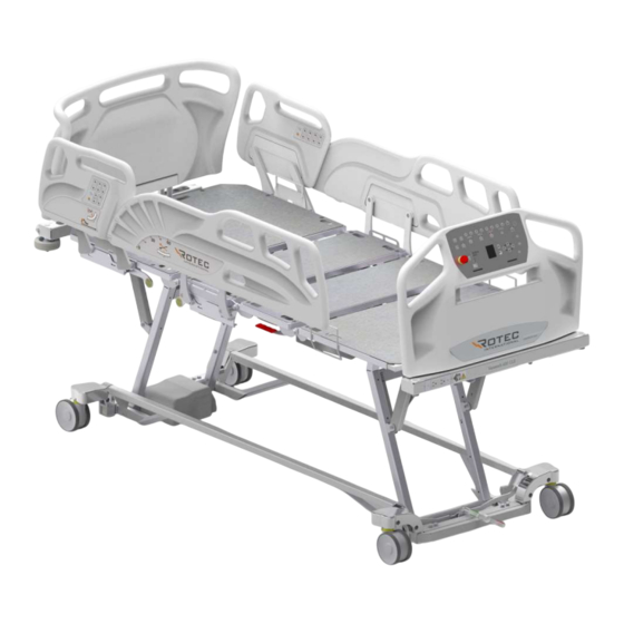
- Page 8 1.3 GENERAL 1.3 Illustration Wall Side panel- bumpers mounted controls Side panels Nursing controls Head section Auxiliary socket Seat section Thigh section Feet Brake section pedal DOC01-V6ULB+...
- Page 9 1.4 GENERAL 1.4 Features 1.6 Accessories Height-adjustable low-profile bed base Mattress, 9 kg (20 lb) Reclining bed platform Trapeze bar, 11 kg (23 lb) Length-adjustable platform I.V. Pole 0.5 kg (1.1 lb) Reclining backrest section ...
- Page 10 1.8 GENERAL 1.8 Certifications Electrical specifications suite Model VersaTech 600 ULB+ CAN/CSA C22.2 No. 60601-1:14 Insulation Class I CAN/CSA C22.2 Rated voltage 120/220/230/240 VCA Cycles 50/60 Hz No. 60601-1-6:11+AMD1:2015 Maximum current 120V model CAN/CSA C22.2 With auxiliary outlet: 8.75 A No.
- Page 11 1.11 GENERAL 1.11 Electromagnetic compatibility (EMC) This hospital bed complies with the following electromagnetic compatibility standards. Standards and test name Compliance CISPR 11 (2015) A1 (2016) Conducted emissions Group 1 - Class B 150kHz-30MHz CISPR11 (2015) A1 (2016) Radiated emissions (Prescan 3m) Group 1 - Class B 30MHz-1GHz CISPR11 (2015) A1 (2016) Radiated emissions (10m) Group 1 - Class B 30MHz-1GHz...
- Page 12 2.1 INSTALLATION 2 INSTALLATION 2.1 Power supply At any time, the main voltage on the device can be safely removed by disconnecting the power cable from the device connected to the wall socket provided for this purpose. Ensure that the power cable is accessible at all times. Please note that this is a Class I device and must be plugged into an earthed socket.
- Page 13 (see section 3). Disconnect the power cable and operate the motors to check the battery. If any damage or malfunction appears on the bed, please contact Rotec International's technical service department without hesitation.
- Page 14 2.3 INSTALLATION 2.3 Positioning in the environment To install this model, the bed must be placed horizontally, at least 127 mm (5 in.) from the wall. Similarly, check that no objects obstruct the end of the foot section, then apply the brakes (see section 3.2).
- Page 15 2.4 INSTALLATION 2.4 Mattress installation/replacement To install a mattress on the unit, please use a mattress that complies with the recommended mattress dimensions. In addition, please ensure that the mattress selected matches the configuration of the platforms chosen. (See mechanical specifications).
- Page 16 3.1 OPERATING INSTRUCTIONS 3 OPERATING INSTRUCTIONS 3.1 Electrical bed functions Symbols Descriptions Up arrow: adjusts the various functions of the device upwards. Down arrow: adjusts the various functions of the device downwards. Backrest function: tilts the backrest section up or down. Press the nearby up or down arrow to engage the actuator.
- Page 17 3.1 OPERATING INSTRUCTIONS The recessed button locks all the device's movement functions on the remote control and controls them fixed on the bed sides and at the foot of the bed, except for the CPR function. Chair function: places the bed in the chair position. This function tilts the back and thigh section upwards, adjusts the height of the foot section upwards and tilts the bed so that the foot section is lower than the head section.
- Page 18 3.1 OPERATING INSTRUCTIONS WARNINGS ON THE USE OF ELECTRICAL FUNCTIONS If the user's state of health requires it, and for his/her own safety, lock the bed's movement functions intended for use by the patient and place the bed in the lowest position, with the platforms horizontal and the bed sides rails raised;...
- Page 19 3.2 OPERATING INSTRUCTIONS 3.2 Moving the unit To move the unit, we recommend raising the base by at least 150mm (6") from its lowest position, to facilitate access to the foot pedal. To operate the system, place the foot pedal in one of three positions: DIRECTIONAL NEUTRAL BRAKE...
- Page 20 3.3 OPERATING INSTRUCTIONS 3.3 Side rails guards To open one side of the bed, use 2 hands, with one hand on the handle and the other pushing the lever located under the bed frame, move the half-rail downwards with a rotating movement, move the half-rail until it stops in its lowest position.
- Page 21 3.4 OPERATING INSTRUCTIONS 3.4 Angle indicators The backrest in relation to the floor The angle of the backrest in relation to the ground is approximated by looking at the measurement (in degrees) indicated by the ball at its lowest point. Backrest to seat The angle of the backrest in relation to the seat is approximated by looking at the arrow (head side) which points to the degrees inscribed on the foot side.
- Page 22 3.5 OPERATING INSTRUCTIONS 3.5 Bed length extension * We recommend raising the foot section as high as possible to facilitate use of the platform's length extension. 1) Press and release the latch on the underside of the foot frame extension; 2) Pull on the foot frame extension ;...
- Page 23 3.6 OPERATING INSTRUCTIONS 3.6 Headboard and footboard installation To install a bed end panels, slide the two (2) rods, from the head or foot board, through the two (2) holes provided until they reach the bottom, as shown below. To remove the panel, follow the reverse procedure described above.
- Page 24 3.7 OPERATING INSTRUCTIONS 3.7 Foot section angle adjustment When raised, the end of the foot section of the bed platform can be lowered as required. To do this, simply lift the end of the foot section (step #1). The mechanism should unlock. Then lower the foot section until it reaches the lock (step #2).
- Page 25 3.9 OPERATING INSTRUCTIONS 3.9 Drainage bag hooks The two (2) hooks designed for drainage bags are located below and on either side of the foot section of the platform. WARNINGS DRAINAGE BAG Do not lower the base to its minimum height when drainage bags are hooked under the seat section.
- Page 26 3.10 OPERATING INSTRUCTIONS 3.10 Openings for restraint belts The openings for the restraint straps are located on each side of the platform. It is the responsibility of the medical staff to use restraint straps properly and to choose which openings to use. WARNINGS ON RESTRAINT BELTS ...
- Page 27 3.11 OPERATING INSTRUCTIONS 3.11 Trapeze bar installation (optional) Insert the trapeze bar into its receptacle, taking care to align the positioning stop with its notch. Designed for Rotec trapezes bar. POSITIONING STOP NOTCH FINAL POSITION Make sure the trapeze bar is correctly positioned by attempting to move it by turning it.
- Page 28 3.12 OPERATING INSTRUCTIONS 3.12 Traction frame support Here are the locations for installing the traction frame. 7/8" diameter opening. Devices for Traction frame Devices for Traction frame WARNINGS TRACTION FRAME SUPPORT Do not use the Trendelenburg function when the traction frame is installed on the bed.
- Page 29 3.13 OPERATING INSTRUCTIONS 3.13 Mechanical CPR To use the function, pull the CPR handle located under the thigh section of the platform as shown below to lower the backrest section only. WARNINGS ON MECHANICAL CPR When activating the CPR function, make sure that no part of the user's body protrudes from the mattress and that nothing is under the bed platform, as this SERIOUS INJURY AND/OR POTENTIAL BREAKAGE.
- Page 30 3.14 OPERATING INSTRUCTIONS 3.14 Nurse call and DB37 output Pressing the nurse call button sends a signal to the on-call station. The bed must be connected to the wall using a DB37 communication wire. The socket for this wire is located under the frame at the head end of the bed. This type of connection is an industry standard.
- Page 31 3.15 OPERATING INSTRUCTIONS 3.15 Integrated scale (optional) The integrated scale option lets you measure a patient's weight. These functions can be accessed via the display and directional keys on the footboard. Main Menu Weighing Menu Settings Menu Use the arrow keys to navigate the menus. The highlighted blue color indicates the current selection.
- Page 32 3.15 OPERATING INSTRUCTIONS WARNINGS ON THE SCALE SYSTEM REFERENCE PURPOSES ONLY AND IS NOT The bed scale is intended for SUITABLE FOR PRECISION MEDICAL USE SUCH AS DOSING MEDICATION. Deactivating the scale also deactivates the bed exit detection system. DOC01-V6ULB+...
- Page 33 3.16 OPERATING INSTRUCTIONS 3.16 Bed exit detection system (optional) Bed exit detection requires no calibration and can warn if there is a variation in the weight measured on the scales. Press one of the buttons described below while the patient is in bed to activate the function.
- Page 34 3.16 OPERATING INSTRUCTIONS Alerting the on-call station is done by connecting to the DB37 output connected to the facility. (See Nurse Call section) There may be a delay of up to 5 seconds before the alarm is activated after motion detection.
- Page 35 3.17 OPERATING INSTRUCTIONS 3.17 Auxiliary output (optional) If the bed is equipped with an auxiliary power socket, this is located under the footboard. The voltage of the auxiliary socket is that of the mains supply, and the socket capacity may be 2.5A or 5A, depending on the model. This socket is connected to the unit's main power supply via an isolation transformer.
- Page 36 4.1 MAINTENANCE MAINTENANCE 4.1 Cleaning The following precautions should be taken when cleaning the unit: Do not wash with high-pressure water jets. Ultrasonic cleaning and immersion of bed parts are not recommended; Always unplug the bed before cleaning; ...
- Page 37 Failure to comply with these safety instructions could jeopardize the integrity of the bed and result in SERIOUS INJURY. Any replacement of equivalent parts not certified by Rotec International may result in SERIOUS INJURY AND/OR SIGNIFICANT MECHANICAL BREAKAGE AND MAY LIMIT OR VOID THE PRODUCT WARRANTY.
- Page 38 4.3 MAINTENANCE 4.3 End-of-life disposal For safe disposal of the device at the end of its life, follow the steps below: Remove the batteries from the device and arrange for them to be recycled at an appropriate facility. Remove power cables, connectors, motors, circuitry, hand controls and electronic controls from the unit.
- Page 39 4.4 MAINTENANCE 4.4 Troubleshooting guide If you experience any difficulties with the bed and/or any of its components, please consult the section below. If the following or other problems persist, do not hesitate to contact our technical support department. Checks PROBLEMS VERIFICATIONS None of the controls work, whether...
- Page 40 4.4 MAINTENANCE Explanation of acoustic signals Loss of actuator position: 200 msec beep No beep for 200 msec Bed exit alarm : 166 msec beep No beep for 166 msec Fatal error (see section 4.4.3) : 50 msec beep No beep for 500 msec Reset fatal error: 500 msec beep No beep for 50 msec...
- Page 41 4.4 MAINTENANCE Troubleshooting after a fatal error When the control box is in fatal error mode, a fatal error beep will be present every time a button is pressed to alert the user to the condition. In addition, all LEDs will start flashing when the system is in fatal error.
- Page 42 Further, except for the warranty set forth above, Rotec shall not be liable for any other warranty made by any other person, firm or corporation. Rotec reserves the right to substitute materials of equal or better quality for repairs and/or replacements.
- Page 43 If Rotec is not notified of the damage within 24 hours of delivery to the consignee, or if the damage is not noted on the delivery note at the time of receipt of the goods, the consignee may be liable for the full cost of repair and/or replacement of the damaged goods.
- Page 44 6.1 REPAIR PROCEDURES 6 REPAIR PROCEDURES 6.1 QLCI replacement (scale circuit) Tools required : • Flat screwdriver • Cutting pliers Procedure: 1. Raise the bed to its highest position and apply the brakes. 2. Unplug the power cable from the wall socket. 3.
- Page 45 6.2 REPAIR PROCEDURES 6.2 Replacing the main circuit or its battery Tools required : • Flat screwdriver • Cutting pliers Procedure: 9. Raise the bed to its highest position and apply the brakes. 10. Unplug the power cable from the wall socket. 11.
- Page 46 6.3 REPAIR PROCEDURES 6.3 Replacing the power cord Tools required : • Robertson square screwdriver #2 • Flat screwdriver • Socket screwdriver 3/8 • Screwdriver extractor CAUTION! MAINTENANCE OF THE ELECTRICAL SYSTEM MAY ONLY BE CARRIED OUT BY QUALIFIED PERSONNEL. Procedure: 1.
- Page 47 6.3 REPAIR PROCEDURES 5. Lift the backrest and open the electrical box. See battery section. DECLARE SCREW DECLARE 6. Disconnect the white and black wires of the power cable from the junction boxes. MAKE SURE THE BED IS UNPLUGGED. 7. Disconnect green wire from ground pole. 8.
- Page 48 6.4 REPAIR PROCEDURES 6.4 Nurse call port replacement Tools required : • Flat screwdriver • Cutting pliers Procedure: 1. Raise the bed to its highest position and apply the brakes. 2. Unplug the power cord from the wall socket. 3. Using wire cutters, remove the cable ties securing the nurse call connector cable to the chassis.
- Page 49 6.5 REPAIR PROCEDURES 6.5 Bed side replacement Tools required : • 1/2" socket • 3/8" ratchet wrench • Cutting pliers GUARDRAIL CPR HANDLE Procedure: 1. Raise the bed to its highest position and apply the brakes. 2. Raise the backrest section to the highest position (if the controls no longer work, operate the CPR handle and raise the backrest section manually) and lift the side of the bed to be repaired.
- Page 50 6.6 REPAIR PROCEDURES 6.6 Replacement of footboard structure extension Tools required : • Flathead screwdriver • 1/2" wrench • 3/8" wrench • Robertson long square screwdriver #2 LEVER SPRING SPRING OPENING Procedure: 1. Raise the bed to its highest position and apply the brakes. 2.
- Page 51 6.7 REPAIR PROCEDURES 6.7 Replacement of wall bumper(s) s Tools required : • 9/16" wrench Procedure: 1. Raise the bed to its highest position and apply the brakes. 2. Loosen nuts with 9/16" wrench and remove shock absorbers. 3. Reverse the above steps to install the new bumpers. DOC01-V6ULB+...
- Page 52 6.8 REPAIR PROCEDURES 6.8 Replacing a bed wheel Tools required : • 9/16" wrench • 1/2" wrench • Extractor screwdriver • Allen key #3 • Allen key #4 • Allen key #5 • Candle (2) • Hammer Procedure: 1. Raise the bed to its highest position. 2.
- Page 53 6.8 REPAIR PROCEDURES 5. Unscrew screw (A) and nut using hexagonal keys. 6. Remove hexagonal pin (B) by tapping on the end. 7. Unscrew the Allen screw (C) and remove the wheel. Note: Orient correctly before installing on the base. The illustration below shows the direction in which the wheel should operate when activated.
- Page 54 6.8 REPAIR PROCEDURES 9. Check that the brakes are working properly before putting the bed back into service. Note: If the wheel does not brake properly, there is an adjustment under the wheel. Using a #4 Allen key, turn one quarter-turn at a time in either direction until the desired result is achieved (counter-clockwise to tighten, clockwise to loosen).
- Page 55 6.9 REPAIR PROCEDURES 6.9 Replacing a load cell Tools required : •Tools for removing the wheel (see previous section) • 3/4" socket wrench and ratchet •9/16" wrench • Magnet Procedure: 1. Unplug the bed's power cord from the wall socket and raise the bed to its highest position.
- Page 56 6.9 REPAIR PROCEDURES 5. Undo the bed wheel as described in the previous section. 6. Remove the cover using the screwdriver extractor. 7. Remove the 3 bolts screwed into the cell. 8. Remove the plastic cover where the wires enter the axle. 9.
- Page 57 6.10 REPAIR PROCEDURES 6.10 Foot section motor replacement Tools required : • 9/16" wrench • Flathead screwdriver • Cutting pliers Procedure: 1. Raise the bed to its highest position and apply the brakes. 2. Position platforms horizontally. 3. Unplug the power cord from the wall socket. 4.
- Page 58 6.10 REPAIR PROCEDURES 5. Disconnect the motor cable (A) by removing the lock (F) with a flathead screwdriver, pressing down on both sides. Lock (F) 6. Using a 9/16" wrench, retain the 2 screws (C and D) and, using another 9/16" wrench, loosen the nuts (B).
- Page 59 6.11 REPAIR PROCEDURES 6.11 Backrest section motor replacement Tools required : • 9/16" wrench • Flathead screwdriver • Cutting pliers Procedure: 1. Raise the bed to its highest position and apply the brakes. 2. Raise the head section. 3. Unplug the power cord from the wall socket. 4.
- Page 60 6.11 REPAIR PROCEDURES 5. Disconnect motor cable (A) by removing lock (F). Use a flat- blade screwdriver and press on both sides to remove the lock. Lock (F) 6. Using a flathead screwdriver, open the motor cover. Trigger 7. Move the trigger release and remove the cable from its base.
- Page 61 6.12 REPAIR PROCEDURES 6.12 Replacement of lift motors Tools required : • 9/16" wrench • Flathead screwdriver • Cutting pliers • Jack stand • Screwdriver extractor Procedure: 1. Raise the bed to its highest position and apply the brakes. 2. Support the top frame on the jack stand. DOC01-V6ULB+...
- Page 62 6.12 REPAIR PROCEDURES 3. Lower the side panels and raise the head section. 4. Unplug the power cord from the wall socket. 5. Using the screwdriver extractor, remove the seat platform cover. 6. Using wire cutters, remove the cable ties securing the motor cable to the chassis. 7.
- Page 63 6.13 REPAIR PROCEDURES 6.13 CPR handle replacement Tools required : •7/16" wrench • Robertson screwdriver Procedure: 1. Raise the bed to its highest position and apply the brakes. 2. Unplug the power cord from the wall socket. 3. Locate the CPR handle. Support Lead 4.
- Page 64 6.13 REPAIR PROCEDURES 7. Reverse the above steps to install the new handle. 8. Check that the handle is working properly before putting the bed back into service. DOC01-V6ULB+...
- Page 65 6.14 REPAIR PROCEDURES 6.14 CPR cable replacement Tools required : •7/16" wrench Procedure: 1. Raise the bed to its highest position and apply the brakes. 2. Unplug the power cord from the wall socket. 3. Locate the CPR handle. Support Lead 4.
- Page 66 6.15 REPAIR PROCEDURES 6.15 Foot lift frame replacement Tools required : • 9/16" wrench • Robertson #2 screwdriver • Jack stand • 3/8" ratchet wrench • 9/16" socket • 5/8" socket • 5/8" wrench DOC01-V6ULB+...
- Page 67 6.15 REPAIR PROCEDURES Procedure: 1. Raise the bed to its highest position and apply the brakes. 2. Stretch the foot extension and support it on the jack stand. 3. Raise the foot section. 4. Unplug the power cord from the wall socket. 5.
- Page 68 6.15 REPAIR PROCEDURES 6. Using a 5/8" wrench, retain the screw (H) and with the ratchet wrench and 11/16" socket loosen the nuts (J) connecting the lifting frame section and the power link (I), taking care to retain all parts and note the location of the nylon washers (K). 7.
- Page 69 6.16 REPAIR PROCEDURES 6.16 Head lift frame replacement Tools required : •9/16" wrench • Robertson #2 screwdriver • Jack stand • 3/8" ratchet wrench • 9/16" socket • 5/8" socket • 5/8" wrench DOC01-V6ULB+...
- Page 70 6.16 REPAIR PROCEDURES Procedure: 1. Raise the bed to its highest position and apply the brakes. 2. Support the top frame on the jack stands. 4. Raise the head section. 5. Unplug the power cord from the wall socket. 6. Using a #2 Robertson screwdriver, unscrew the screws (G) from the plastic eyelets (F) holding the load cell cable.
- Page 71 6.16 REPAIR PROCEDURES 7. Using a 5/8" wrench, retain the screw (H) and with the ratchet wrench and 11/16" socket loosen the nuts (J) connecting the lifting frame section and the power link (I), taking care to retain all parts and note the location of the nylon washers (K). 8.
Need help?
Do you have a question about the VersaTech 600 ULB and is the answer not in the manual?
Questions and answers